Not sure what is going on here but when I try to engrave a simple border it puts any text at the bottom left and right (and doesn’t do this correctly) anddraws the rectangle in the right place. Please see the photo below:
Maybe give us some speeds. Can you post a screenshot of the layer settings you’re using?
I see you’re using those wheels on the Y axis at least. That’s the same system my 3d printer uses. I would imagine if you’re pushing the speed too fast, it’d be easy to lose steps with those.
If he would be losing steps he would have to loose a lot of steps because TL shifted all the way to the bottom. Also the rectangle would not output the way it does. Right?
I am glad I am not the only one that thinks its weird!
It kind of doesn’t move from the origin to start the TL (for Top Left) in the bottom left, then shifts over to the bottom right to do the BR, outline first, then moves to do the inside, then does a nice rectangle where it should be!
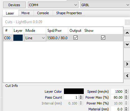
Speads etc. below. Think it is fast and should slow it down. What do you Guys think?
Slowing it down won’t change the speed it runs between cuts or the acceleration, either of which could be the cause. Can you type $$ in the console and press enter, then post what the controller emits? (those are your firmware settings)
These might be too aggressive for that hardware - that’s 200 mm/sec top speed in X & Y (which is how fast your G0 moves will try to go) and the acceleration is 6000mm/s^2, which is really high for a diode machine. Most CO2 systems run less than that. I would drop the acceleration down to about 1500, maybe 1200, and drop the $110 and $111 down to 9000 as a starting point, possibly as low as 6000.
Because the rectangle was run at the line speed of the job (1500mm/min). The jog move between the TL and BR moves would be run at the max speed of the controller (12000mm/min), accelerated to at 6000mm/s^2, and your machine isn’t likely capable of either of those, much less both together.