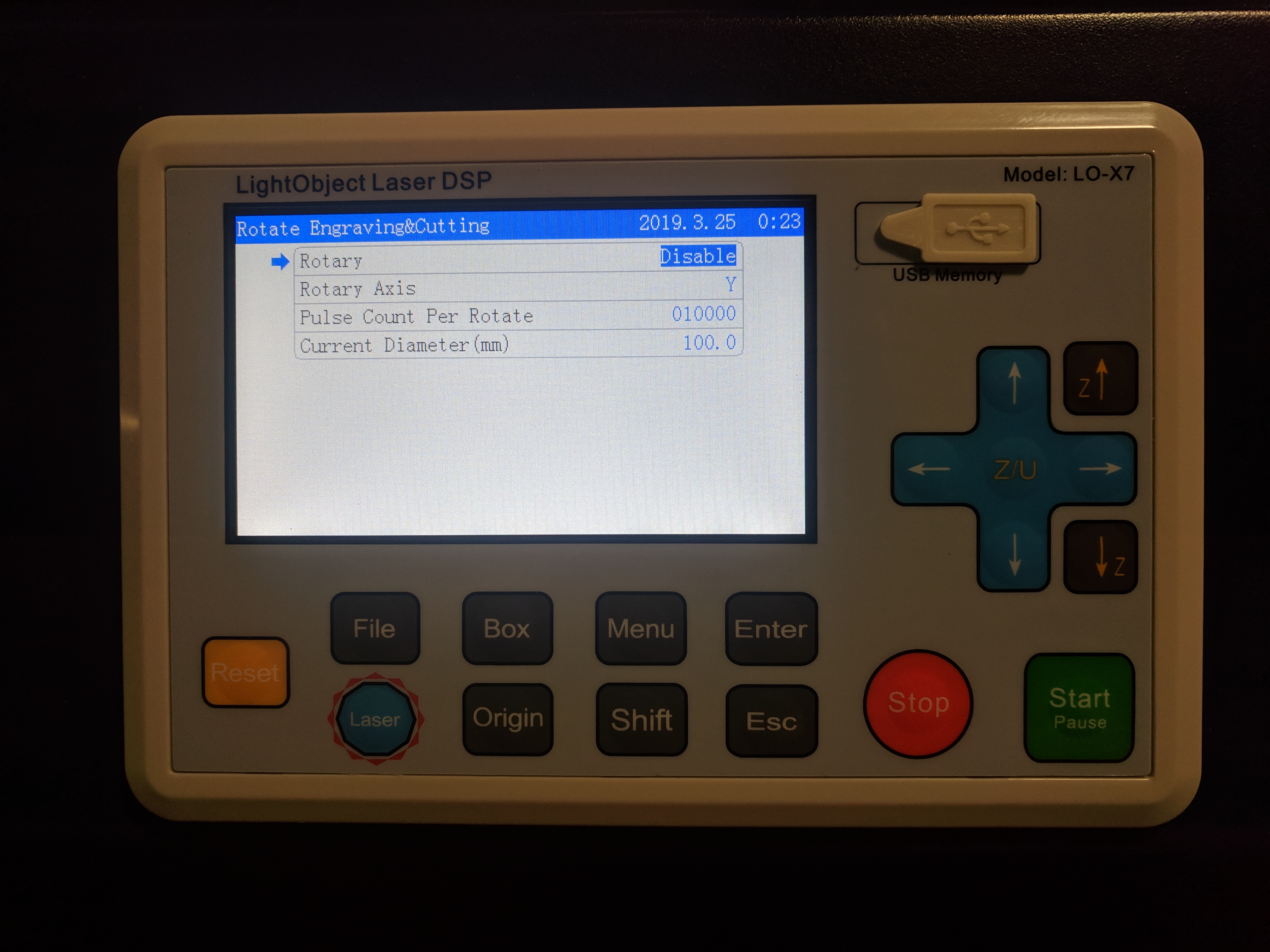
So got my U axis rolling. I did an engraving on a glass mug and it is all stretched out in what would be the Y axis or the rotation. X is good dimension wise.
I set the pulses per um thinking that would be sufficient just like if I was configuring a Y axis. But in the Rotational settings there is a “pulses per rotate”… Is there some way to calculate that?
In another thread in the section he talks about it but doesnt give any further information on how he was sucessful. Any help is greatly appreciated.
What isn’t that doesn’t work as expected? I enable rotary which then switches feed to the U axis instead of the Y. My only problem is that it seems to stretch the design out. Increasing the the “pulses per rotate” is tightening it up but there must be some way to calculate what that number should be… but I cannot thing of how. I took the pulse per um, then multiplied that by circumference… that didn’t put me anywhere near where I think I should be… probably somewhere around 17000 pulse per rotate. If you need someone to help test this feature for next release let me know.
If your rotary is direct drive, i.e. the stepper motor is coupled directly to the roller or chuck, the steps per revolution of the stepper motor are the same as the steps per rotation of the rotary. It’s just the steps per revolution of the motor multiplied by the number micro-steps.
To calculate the steps per rotation of a belt driven rotary device,
S = steps per revolution of the stepper motor
u = # of micro-steps
MP = # of teeth on stepper motor pulley
RP = # of teeth on roller/chuck pulley
(S×u×RP)/MP=steps/rev
For example:
A standard NEMA 17 motor is typically 1.8° per step or 200 steps per revolution. Many of the stepper drivers are set up for 32 micro-steps. A common pulley size on the motor is 20 teeth and let’s say the roller pulley had 50 teeth. Plugging all the variables into the formula,
(200×32×50)/20=16000
so this hypothetical rotary is 16000 steps per revolution.
Ugh I didn’t even think of that calculation cuz of the stupid chinglish wording used in the interface totally screwed me up. I bet 16000 is my magic number. It’s a typical nema 23 and the driver is at 1/32nd micro-stepping and judging by the size of the pulleys they are probably 20 teeth. Thanks man!!
So went and looked at it this morning, what I have is nema 23, driver was set to 16 i changed to 32. Motor pulley is 24 teeth, roller pulleys are 36 teeth. So using this math I have 200x32x36/24=9600… that doesnt seem right. If it was a 0.9 degree motor then would be 19200 seems more right. Does the size of the roller have anything do to with anything?
The NEMA size isn’t important here. You need to know the total steps per revolution of the motor. Typical step sizes are 1.8° and 0.9° which would yield 200 and 400 steps/rev respectively. You’ll have to look up the part number on the motor to find out what step size it has.
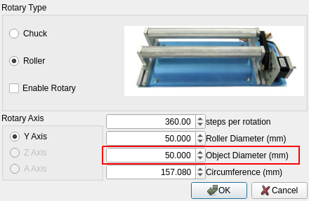
The steps per rotation of the rotary isn’t the end of the story. If you go to rotary setup in LB, you’ll see you also need to know the diameter (in mm) of the roller and the object. The steps per rotation, roller diameter, and object diameter all come into play. If any of them are wrong, you’ll get a compressed or stretched engraving.
I got it… I didnt have to set anything up in LB. I didnt enable the rotary at all in LB. I just enabled in on my machine, set the Pulse Count per rotate, put in the diameter of the work piece and it worked… Now to try a different size glass and see what happens.
Yes that one… But with this new piece of glassware I am trying the “current diameter” doesnt seem to be working the same way. It is squishing the design now. I have lowered the current diameter setting down a fair bit and it is stretching it out now. But it doesnt correspond to the actual diameter of the work piece
When you click enable rotary does it then ignore the pulse per um setting for the Y axis normally, and use the steps per rotation setting set in the rotary settings in LB? I am using the U axis to avoid having to constantly calibrate Y as I go back and forth.
I don’t know. I just installed this controller and don’t have a ton of experience with it yet. I would assume it ignores the um setting because it isn’t relevant for the rotary. If you’re using the Y-axis, I wouldn’t enable the rotary on the controller. I would let Lightburn handle all of the calculations.
I know adjusting the pulse per um for the U axis definitely effect how far the rotary turns. I wonder if I adjusted it wrong. I did it in the glass I was using. Maybe adjust to the roller wheels so they always turn the same number of pulses per um then adjust work diameter… I will have to test this theory later
Hmm I was watching some vids on youtube and its was for a ruida but I think the setting is the same. The “current diameter” in the rotate and engraving menu I think that number is supposed to be the diameter of the rollers and that should never change. but i am still stuck on how we compensate for different diameter materials on the rotary. or does that even matter…