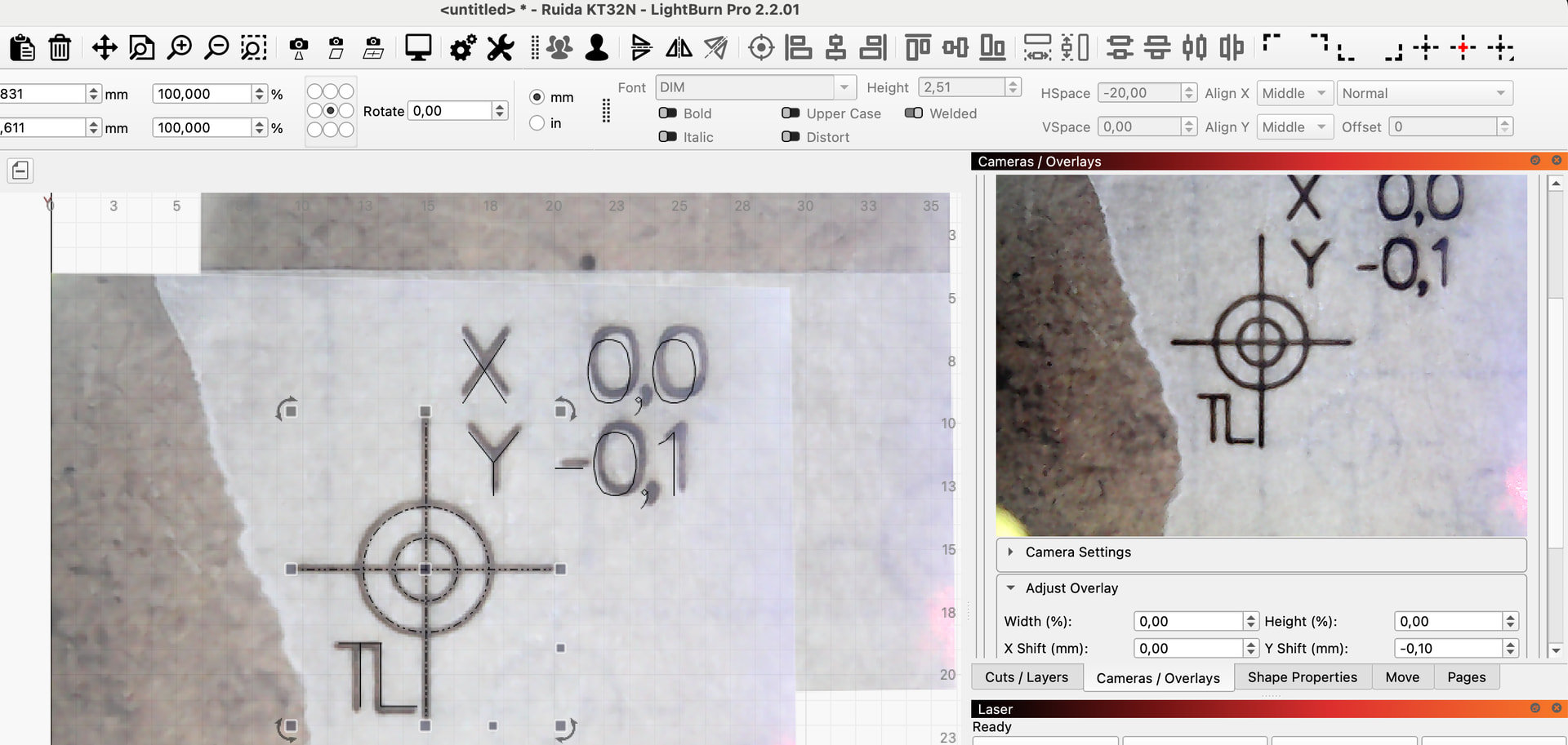
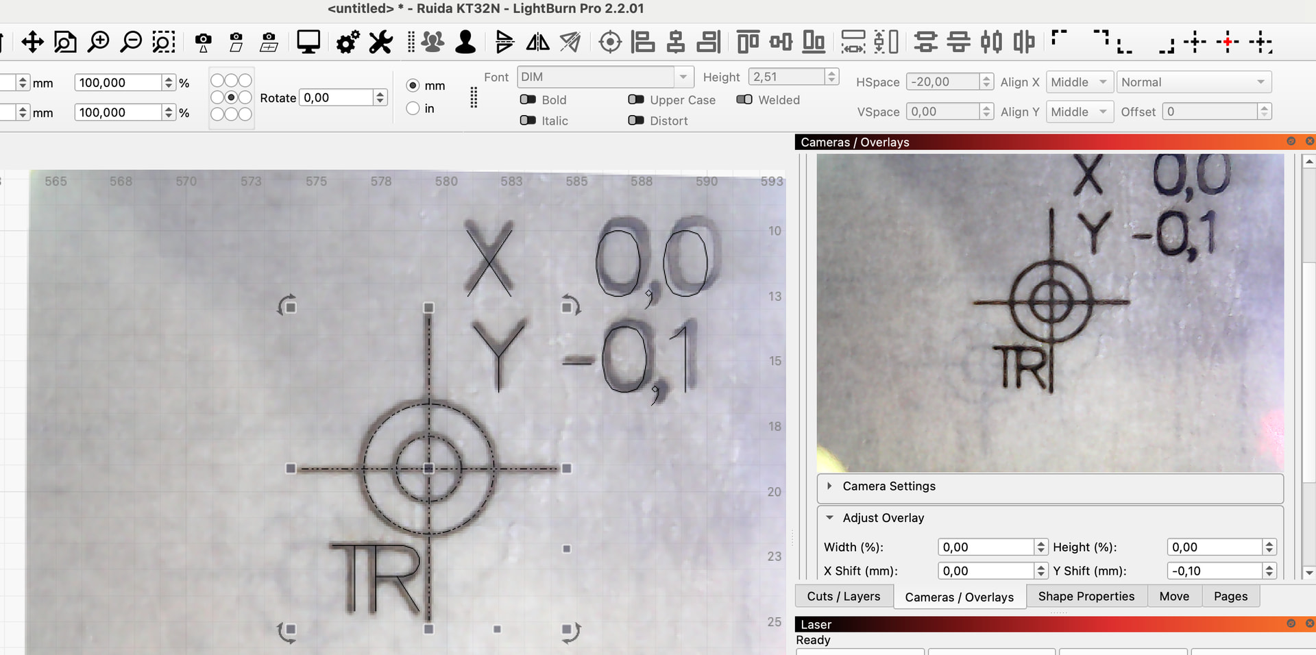
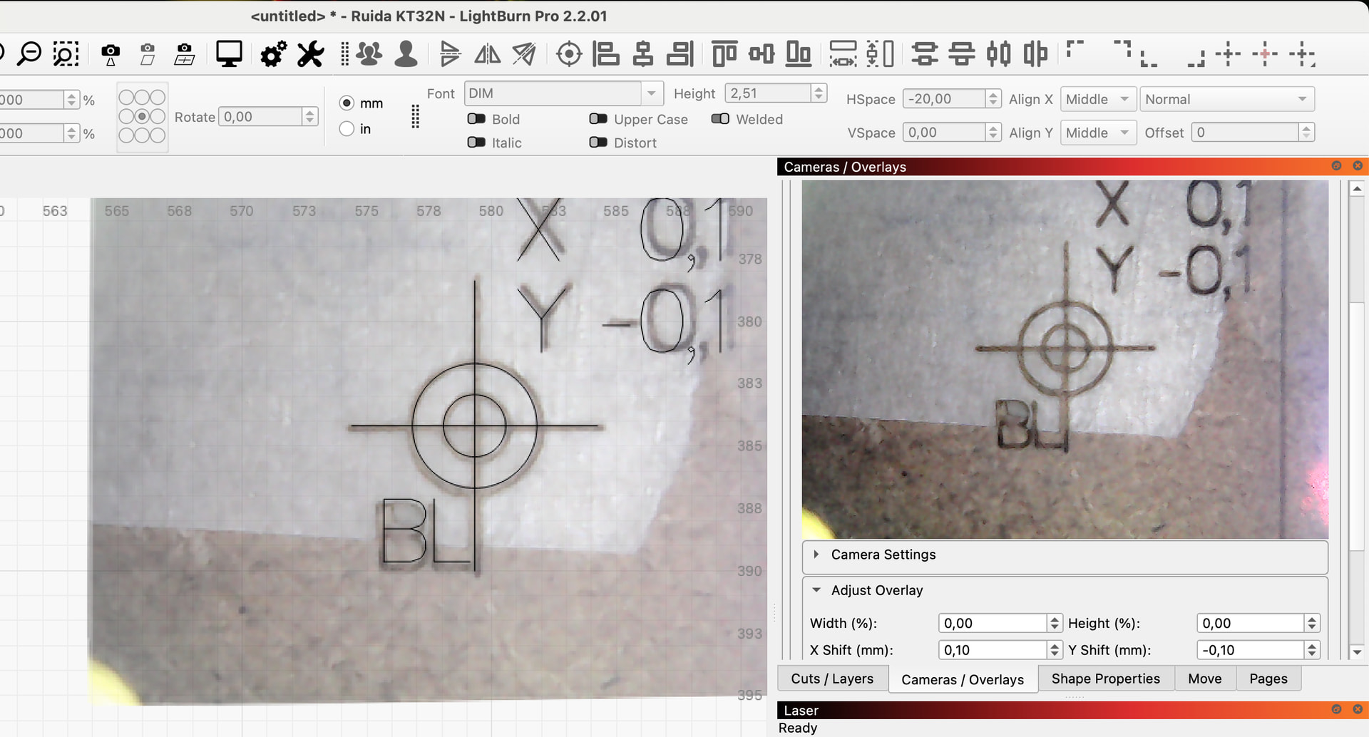
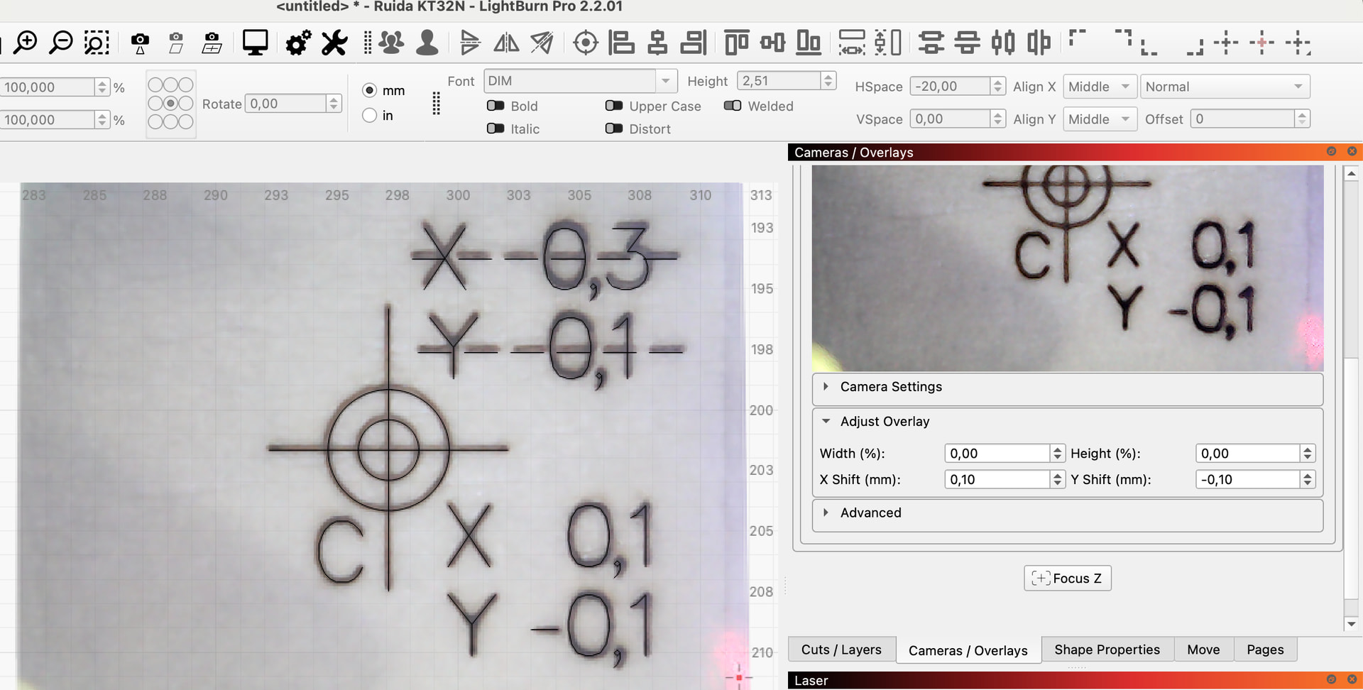
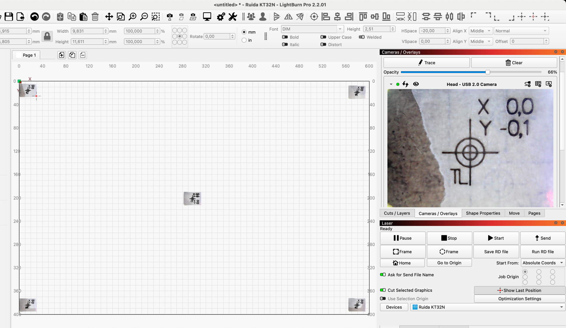
In the last few days I have finally had the opportunity to test and play with the new camera supported version of Print & Cut.
There must be a lot of development going on in this sector, tests in RC8 did not work for me, but in the latest 2.2.00 version it also works here now.
… not completely problem-free, (I also managed to send some bug reports to LB), but if you follow some rules it works extremely precisely.
One of the main problems is that it is relatively difficult to calibrate the lens, and workspace afterwards. The lens of my small endoscope camera has a visible/usable area of 28x20mm. This makes it so difficult to use AprilTags and the subsequent alignment print.
On my (MacOS) system I cannot switch between the original fixed camera and the head-mounted camera, which would otherwise make work much easier. Without that option I have to physically place the laser head over the targets and approve/start from the computer. Control of the movements is also not possible because the distance between the nozzle and the camera is larger than the field of view of the camera lens. This it could be changed by placing the camera high enough or at an angle to the nozzle’s height-calibrated focus point. However, this would have the fatal effect that camera precision is lost.
Despite the difficulties, the result of Print & Cut is excellent - if a few rules are followed.
It is crucial that the manual placement of the camera of the numbered 4 targets is followed and that the orientation (between P&C file and the physical item at the workplace) does not exceed 12.5 degrees, or does the camera also have to be guided manually for the mark 2. With up to a maximum of 10 degrees deviation from the print to the overlay, I get precise results, i.e. 0.02 mm for all 4 targets, internally corrected.
Paper drawings cut in this way have no visible edge from the material that should not be cut.
LB recommends setting the reference marks to “no output”, understandable enough, but this also makes the marks paler and harder to see. A dark T3 with fill option is missing 
The handling of the process (targetfinding) needs to be improved/simplified and the camera handling needs to be stable, but it should not be forgotten that it is “only” a “Labs” tool yet. And for those who need “Print & Cut” at a higher level, this tool with its fantastic precision is already very valuable.
What surprises me is… it should be possible to achieve the same result with the overhead camera. The 6mm filled circles, which work best with the head mounted camera, are seen and recognized well with this camera too. I wonder if the software can be used to calculate the optical deviation when there are 4 numbered or specific control marks?
What I mean is, in contrast to the existing classic print and cut, with its 2 reference points, the camera could take over this job
The latest API activities also point in this direction, to make it possible to automate the placement of shapes and objects in LB with the help of the camera.
Exciting future