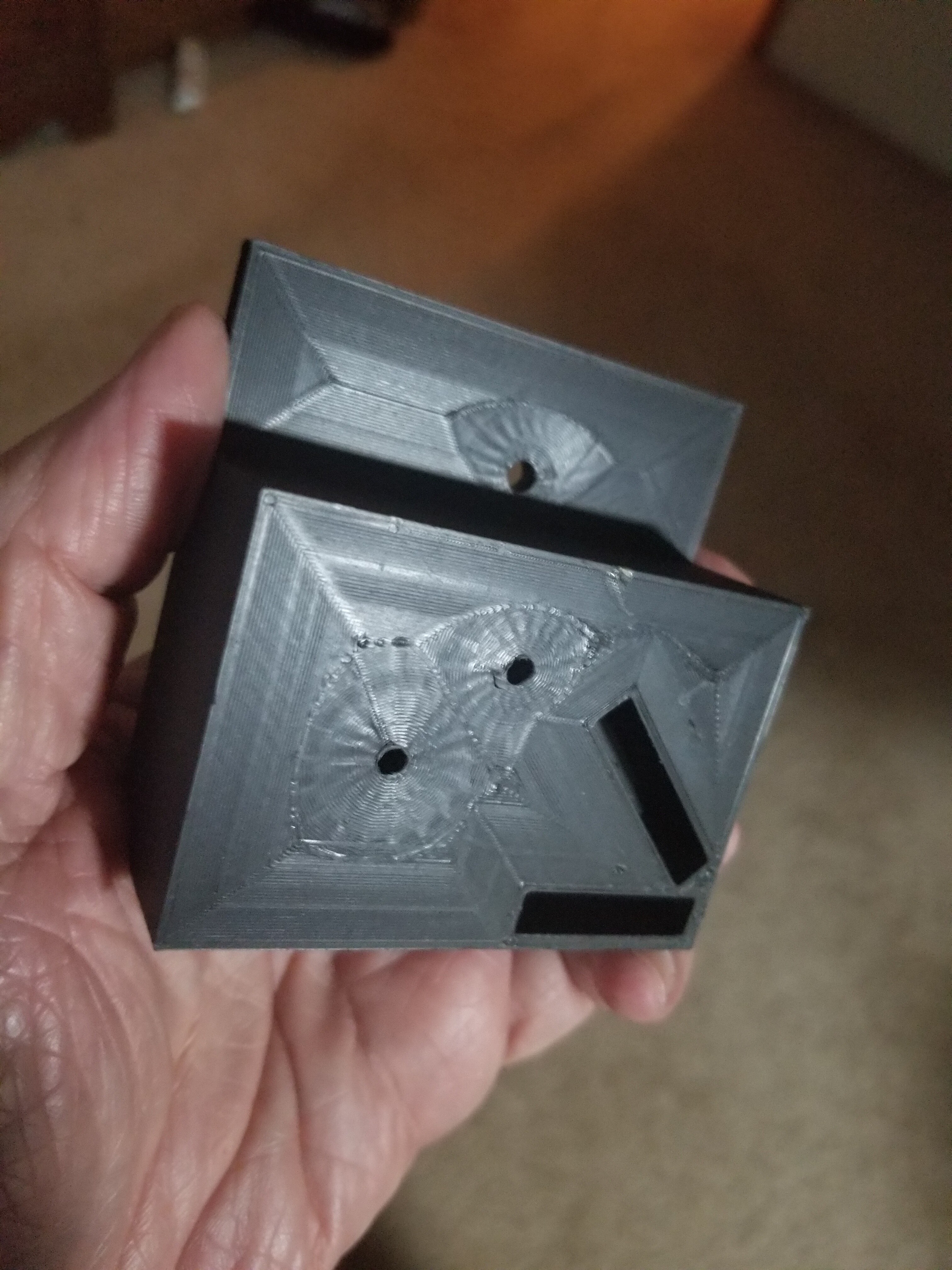
This is one of my many versions. Two holes for the mirror. Press fit for the two mounts. The mirror holes have counter sinks for the screws I stole from ther red laser mount.
1 Like
I’m going to be away from my computer for awhile so I decided to upload my freecad file, warts and all. The file type isn’t approved. I have to figure out where to put it so I can link to it. I’m not sure if it would even be useful.
Does it work if you change the file extension .txt?
Sometimes you can get around the file type problem that way. Remind folks to change it back to the proper extension after download.
k40mirror.txt (387.8 KB) I tried txt file upload and verified it works. Change txt to FCStd. I have no problem with people modding it. Cleaning it up and publishing it is also OK. Just don’t use my name. 
All of the origin coordinates for the solids are the center of the mirror or laser. The three mirrors and the laser then have the same Z position.
Mirrors #1 and #2 have the same X position. This showed that adjusting them so the mirror holders were the same distance from the wall was wrong because the mirror isn’t centered in the holder. It was a major improvement for me.
The mirror #1 and the laser stand are aligned by touching walls. The other mirror adjustments are made by several measurement attempts. These measurements need to be named. The main reason for the reluctance to sharing.
1 Like
Alternative Solution to this problem.
I went for a simpler and less costly solution to this problem.
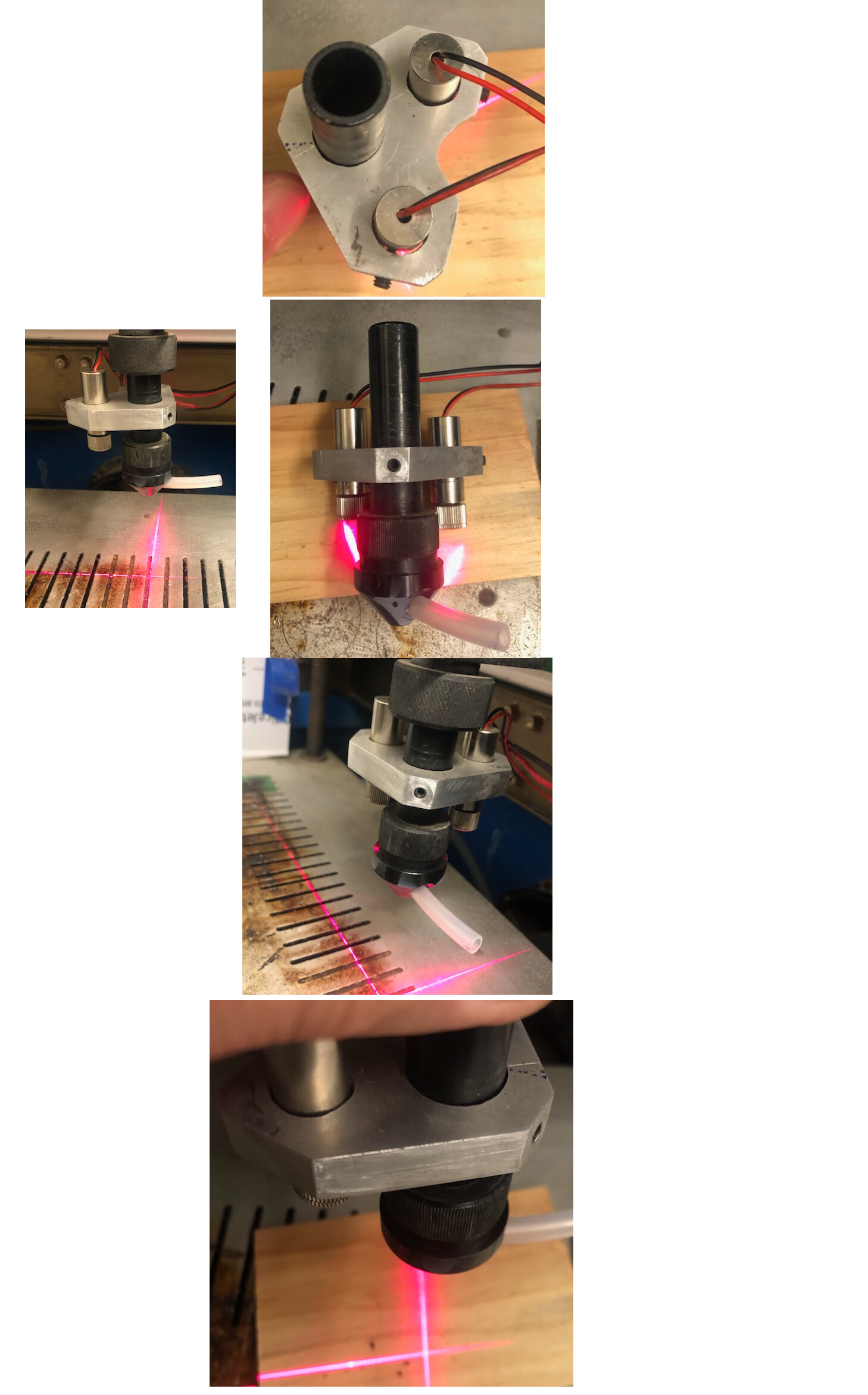
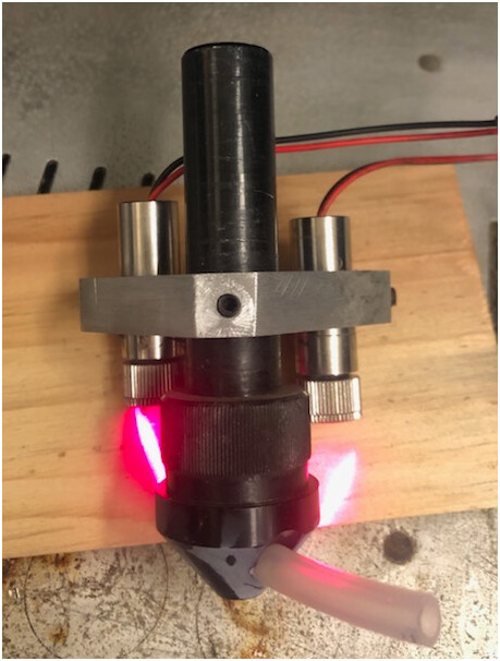
I used a 1/2 thick piece of aluminum and drilled 3 holes.
One at the center the diameter of the Laser Tube.
And on a 90º Axis drilled Two holes the diameter of my “Red Laser Beams” purchased off of Ebay.
I drilled and tapped holes for Three Set Screws to hold each Red Laser Beam and the Laser Tube in Place.
I had to use Lock Tight to set the two Red Laser Beams focus.
I used the LINE function not the DOT on the Red Laser Beams.
Adjust the two Red Laser Beams to where you Laser Cuts.
You shouldn’t have to adjust it after that no matter how you adjust your Laser Bed.
I hope this helps someone.
Respectfully
Karl
3 Likes
Nice solution Karl. I have been using a similar setup with just one laser and it has been working ok for tha last couple of years. I often ran in to a problem that it lost me some adjustment of the height of the tube (I don’t have a moving Z axis), and another time I messed up a couple of jobs because the bracket had been knocked. So I thought it was time for something different.
Cheers
David
1 Like
For my K40 there are a number of 3D printed nozzles with space for a fan and 1 or 2 small laser pointers. I have used this system with the 2 lines and am always in focus. Your aluminum solution is a fine, small and stable craft.
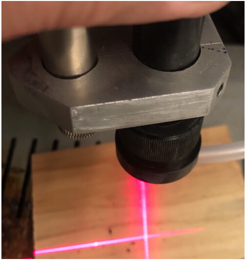
The two line laser option has been used for a while by many and they seem to like it. As you mentioned, because the laser lines are 90% off from each other and along their axis to the beam, they will always cross in the same spot no matter the distance from the nozzle.
I opted for the beam combiner since I didn’t want to add any weight or material to the laser head since it moves quite fast during engraving and even a small mass gets amplified when accelerating and decelerating at a few hundred mm/s.
FWIW, I will be modifying my beam combiner/red dot laser holder( K40 laser cutter Combiner Mount for red dot laser by DOugL - Thingiverse ) to hold a 25mm American Photonics beam combiner. Currently it’s designed to hole a combiner I got off a random piece of medical equipment so this update means people can actually purchase a beam combiner to fit. I should be done in a week or two. This is the combiner I plan to create the mount for: Amada, Bystronic, Cincinnati, Co2 Cutting Machine, Co2 Laser, Debris Shield, Fiber Collimator, Fiber Laser, Fiber Laser Cutting Machine, Fiber Lens, Fiber Protective Windows, Focusing Lens, High Power, Laser Mech, Laserlab, Mazak, Mitsubishi, Precitec, Prima, Raytools, Strippit, Trumpf – American Photonics
Well my combiner kit has been dispatched, heaven only knows when it will get here, but I’ll be sure to post some pictures once it’s up and running.
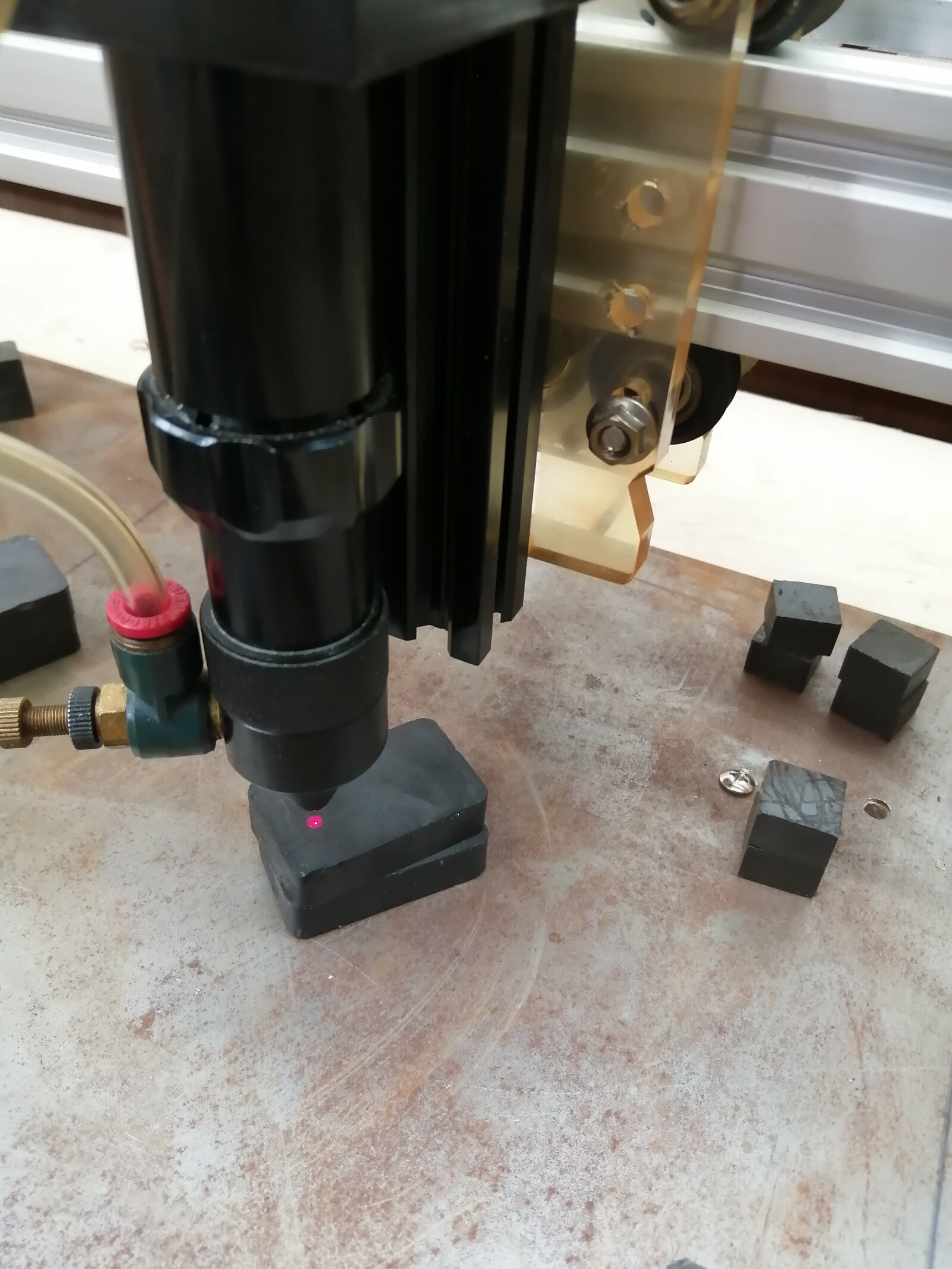
I like the idea behind the beam combiner, but I found that I enjoyed having the simple red dot coming from an angle because when placed correctly, it allows me to check or adjust focus really easily
It’s on the left of my laser head, and when the focus is right, the dot is perfectly below the nozzle.
If I see that the dot is a little bit on the left, I know I’m too high, and if it’s on the right then I’m too low.
When I got my laser cutter I thought I’d get a beam combiner but I changed my mind.
Having a laser pointer attached to the head is not a perfect solution, but the beam combiner is not perfect either, the semi transparent mirror is not as reflective as the mirrors we typically use
I really like the idea of having 2 line lasers crossing below the nozzle, great idea. Of course it adds weight so there’s that.
Oh and also, there is the camera function of lightburn which is really awesome
1 Like
Good points @Fardenco and indeed a correctly aligned single dot laser pointing at the focal point can be a quick reminder you had not focused. Myself, I learned from using an old Epilog laser that having a piece of material you hang from the top of something on your laser head and sized so it will fall off when you raise the bed to the proper focal point is so easy to make and use I only use the red dot of the combiner to positioning now.
And as you mentioned, with the camera system in LightBurn, even positioning the laser on the bed and work piece can be done without any visible laser at all. But like how you use the laser head mounted angled red dot laser for visual information, I still find the beam following combiner a visual indicator of things.
I even use it to indicate to me how well my airflow/extraction is by if I can see the red beam in smoke up at the mirrors. When I do, I’ll crack open the lid or close it to keep the smoke down and low in the chamber.
Many options and as always, use what works for you.
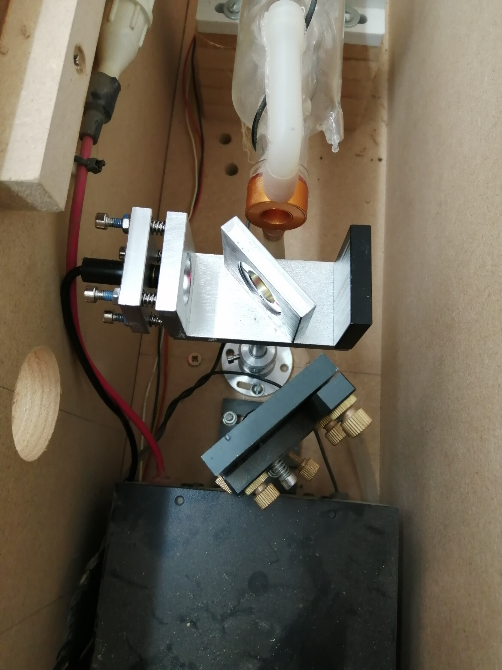
My main goal was not putting a red dot on the material. I wanted the red beam path to follow the laser beam path so I could adjust the mirrors using the red laser instead of burning a bunch or dots in tape. That’s why I put the combiner before mirror #1. I like to play with the laser machine design more than actually making burn projects. As a side affect I have everything in fixed positions instead of positioning with slotted holes over and over again. I had fun, but someone else may not like all the design tweaking.
The red cross method is clever way to use a Z table.
1 Like
I know the feeling @paulf8080 , I really like improving things and often spend more time there than using the machine which is 180 out from what most people do. Soon I will have LinuxCNC on a Raspberry Pi controlling my K40 via its MKS Sbase v1.3( running Remora firmware). My 3D printer(Ender 3) is already running this setup. After the laser upgrade will be the CNC upgrade to the same setup.
I know it doesn’t help you but I updated and published the K40 combiner mount for a red dot laser. It’s positioned after mirror #1 and covers the hole between the laser compartment and cutting area.
Well , my combiner arrived a few days ago from China.
I chose the set without the 1st mirror attached. Quality wasn’t too bad, the hole for the red laser was a little sloppy +0.3mm, but a single layer of tape fixed that.
I did manage to squeeze it in before the first mirror and that made setting up really quite easy. Setting the height with shims was the best way rather than trying to adjust and tighten the screws.
I set the angle between the combiner mount and the 1st mirror to 90 deg with a square and that gave me a good starting point. Set the red laser focus to the longest distance and then fitted it to the stand. Not a great adjustment method, but does the job. I did a standard optical alignment on the CO2 laser first because the slight refraction through the combiner shifted it off. When that was back to normal I did the same with the red laser. In all it took probably 3 hours start to finish. The red dot is of course perfectly aligned with the laser beam and the same size roughly so as accurate as you need. Happy with the result and may even make general maintenance alignment easier.
The dot looks huge in the photo, but in reality it is very tiny.
Thanks for all the messages in this thread, it really started an interesting conversation.
Cheers
David
3 Likes
This topic was automatically closed 30 days after the last reply. New replies are no longer allowed.