Cannot get lighbun to scan faster than 400mm

I have a DIY build with a Ruida 6445g. I cannot get a scan test to run faster than 400mm/s.
Created a 200mm square, if i set speed at 500mm/s, the laser etches dots instead of lines. Laser only moves about 1/2 inch when engraving.

I have enter my bed size correctly. Anyone have any ideas on what could be happening?

thanks,
Bob

Hi Bob,

can you provide more information? Maybe a photo of what is going on or even a video?

Without any further informations it just sounds to me that your stepper motors are not able to go that fast and are skipping steps. That should make a quite distinct noise if that happens so.

Cheers,
Brian

Thanks for getting back to be. I have a video that i can show you.

1 Like

Also noticed this only happens with LINE and not FILL.

If you go in to your machine settings, what are your max X & Y speeds set at?
image

Hey Bob,

very nice looking machine you have there! :smiley:

I still would say that your stepper motors / drivers do not like the acceleration you demand from them for the 500 mm/s engraving. You can simply test this if you save/write down your Ruida sweep settings (on the Ruida DSP (Menu > User settings > Sweep para) or the Engraving Parameters in LightBurn) and afterwards just change the X acceleration value to a fairly small amount to see if your machine will be able to engrave with that.

What this will do is to highly increase the additional space your laser head will have to accelerate and decelerate it’s speed beyond the actual engraving area (which will be paid with more space needed on both sides of your actual engraving area as well as more time that will be needed to do the engrave).
This will be much easier to handle for your stepper motors and your stepper drivers.

If your machine will be able to handle your 500 mm/s engrave with a much lower acceleration you can start to investigate how to increase the overall performance of your steppers.

And as @Hank already mentioned, it might also be helpful if you could share your X Axis Settings as well as your Engraving Parameters from within LightBurn here.

Good luck and cheers,
Brian

Hi Hank,
Its set at 800,


Here are my settings, thank you for the compliment, now my daughter wants it to work. :grinning:

I’m using DM542 Drivers with Nema17 Steppermotor. What setting should i be using on Driver?
Currently set at 25600

Hmm. Well since the machine is “DIY” I don’t know what kind of capabilities it has so can only compare to garden variety chinese machines of the same basic size.

But, the max acceleration on that X axis seems pretty high at 10,000mm/sec^2. Is you machine capable of that kind of acceleration?

And the step length of 1.7548 um?
That’s 570 steps/mm and at a speed of 400mm/sec that’s 227,946 steps per second!
I have to wonder if the controller, stepper driver, and motors are done having fun at that speed.
I don’t know what is “typical” for these machines, but my step length is about 30.06 um which would be a mere 13,306 steps/sec.

Where did that step length come from? Did you do some math to calculate it, or was it just “ruida default”?

Ho Hank,
Pretty much all the settings are default RuidaAll. I’m suspecting that my 542 driver is not setup correctly.

Going to try a lower setting.

If that’s the steps/rev (microstepping) set on your driver then I think you’d be well served to turn it WAY down. 8-10 microsteps/step is about the most that actually does any good. Beyond that is not gaining anything.
Try setting yours at about 2000 steps/rev (10 microsteps/step) and see if that behaves better.
You’ll need to increase that step length in the controller to compensate and end up with the right scaling.

Thank Hank, I turned it down starting at lowest setting and moved up until the axises would move without making noises, i reach 12800. I then tried the engrave and seem to working normally now.

Stepper Motor 17HS19-2004S1
Driver:

Great, sounds like you’re back on the road again!

But I’ll be honest, I think 12800 steps is way too high. This is not a place where “more is better”.
Your steppers almost certainly have a native resolution of 1.8°, or 200 steps /revolution.
Setting your driver to 2000 attempts to divide each of the motors native steps in to 10, for a resolution of 0.18°, which is probably about the most you can reasonably and repeatedly expect from a garden variety (not extraordinarily pricey) motor. Once you go too far on steps/rev you’re gaining nothing and starting to risk an assortment of other problems.
Think of it like setting the DPI on your laser scanned items. There’s a point of maximum goodness and beyond that you’re just wasting system resources and risking lower quality.

Personally, I set my stepper drivers for 2000 steps/rev, because I think that’s reasonable for the 1.8° steppers on my machine. (or most 1.8° steppers in most applications.) I would suggest starting there and doing some research on driving steppers before jacking it up too much higher. Just because “it still works” at that high setting doesn’t mean it’s good.

I guess I didn’t mention it earlier, but your machine sure looks nice. I like it! :slight_smile:

I was able to get it down to 6400, any lower and the axis are not able to move.
Is this beause i need to adjust controller as well, to get the steps even lower?

And thanks for the compliment!

Hey Bob,

I wasn’t able to be around here much for the last couple of days so I’m only just now being able to get back to you. So last things first:

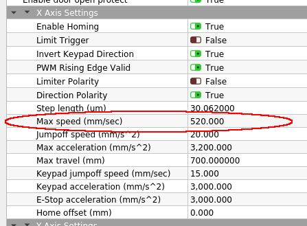
Yes, absolutely! The “Step length (um)” tells the controller how long one step (aka one pulse from the controller to the driver) would move the laser head and therefore how much pulses it has to send to the stepper driver to get your laser head move the requested distance correctly.

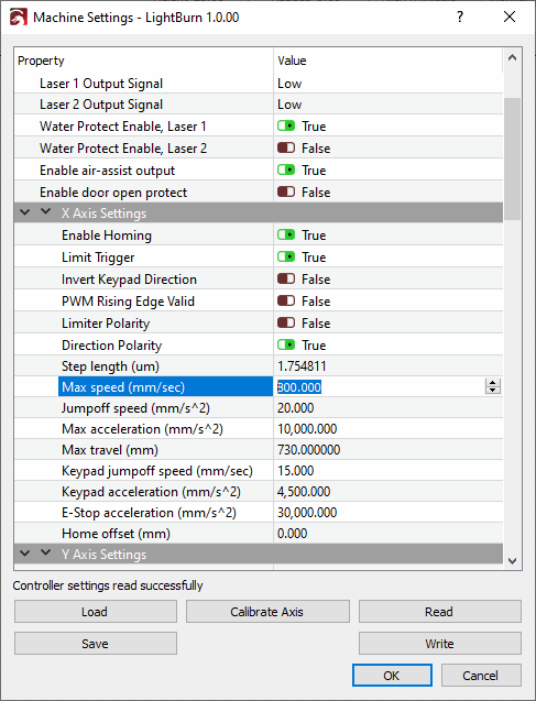
So has @Hank has already nicely pointed out, with a step length of 1.7548 um (which is indeed most probably way to small) and the controller would want to move the head 100 mm it will have to send 56,986 pulses to the driver (or being exact: 56,986 * 1.7648 um = 99,999 um = 99.999 mm).

If this would be correct with your driver being set to 25,600 pulses per revolution and you reduce this on the driver to 12,800 pulses per revolution, the head would actually move 200 mm instead of 100 mm and if you have set the speed to 250 mm/s it would actually move 500 mm/s! You should easily be able to see this effect if you measure the requested moving distance (like 100 mm) and see what the actual movement is.

I’m quite sure that this is the cause you get a wired noise from the steppers if you set the pulses per revolution “too low” as this would end up in a very high speed for your steppers. Reducing it from 25,600 to 6,400 without changing the step length accordingly and still assuming the moving distance was correct with the 25,600 and a set speed of 250 mm/s your head would actually have to move with 1000 mm/s (1 m/s)!

Yet again, if the actual moving distance would be correct with your current setup (which is quite unlikely as you have said that you have never tuned it), you would have to double your step length in the controller if you reduce the steps per revolution by half and so on…

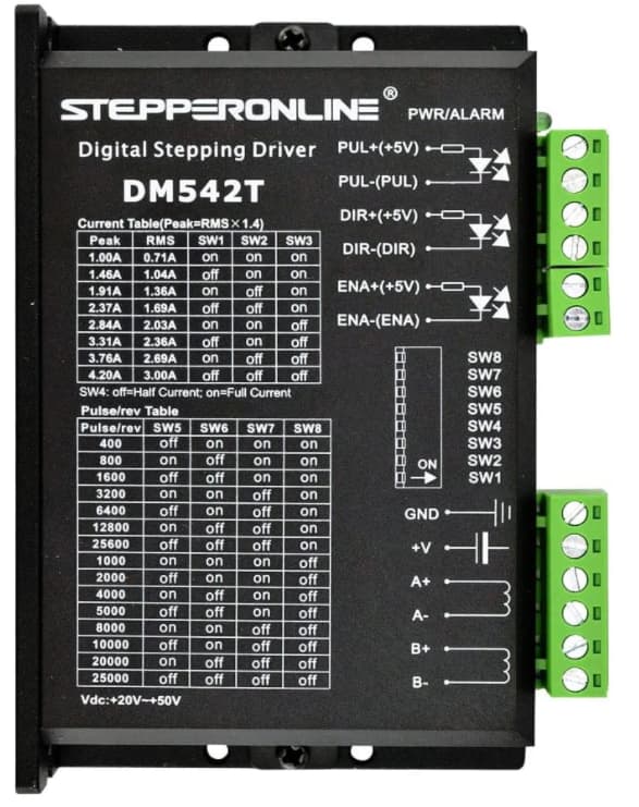
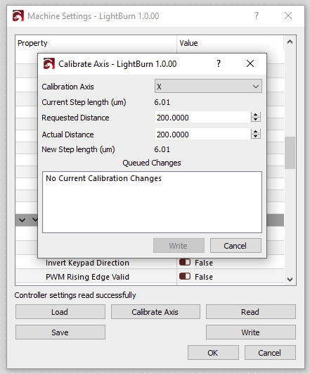
But as you most likely never have tuned your step length you really just should do that first! So set the steps per revolution in your driver to 2000 as @Hank suggested (and I do agree with him that higher is not necessarily better in this case), set your steps length in the controller to say 20.0 and after that start to calibrate that value. Either with the calibration within the Ruida DSP or with the build in feature from LigthBurn under Machine Settings > Calibrate Axis:

And don’t hesitate to ask if something is unclear to you or you have further questions to this! :slightly_smiling_face:

Good luck and cheers,
Brian

No worries, thanks Brian,
I did get it to work at 6400, but i am going to try and get it down even further. When i change driver to use a lower step, the motors shudders. Should i adjust the setting in the console before or after make driver changes?

I would do both before starting to test the values and move the head around. In which order doesn’t matter, just do both. The settings in most drivers do need a reset of the driver to take effect while the settings in the controller do take effect immediately after you have written them to the controller.

Also note that higher values to the step length are less likely to get your drivers to shudder as lower values. That’s because if the value is too high you will move slower than selected (e.g. 50mm/s instead of 100mm/s) and if the values are too low you will go faster than selected (e.g. 100mm/s instead of 50mm/s).

Have you verified that your head movement is correct (e.g. 100 mm are actually 100 mm)?

Totally understand now. Yes i did verify movement 100m on both X and Y.

Is there a formula to determine proper steps, taking into account the gear i am using on the motor? I’m using a 15T HTD 3M gear on both X and Y motors.

Would this be correct?
Diameter 13.56
Radius 6.78
C= 2·3.14·6.78≈42.6mm one revolution

42.6 /2000= .0213um

So with 2000 steps per revolution you would have a step resolution of 0.18° per step. With your

you should probably have a radius of your working belt of about 7.16 mm. With the belt directly driving your head (which should be the case if you have your laser head belt directly connected to the stepper itself without any gear ration in-between) you should be able to calculate the step length with the radian measure like this:

a = revolution per step = 360° / 2000 steps per revolution = 0.18°
b = step length = Pi/180° * r * a = 3.1415/180° * 7.16 mm * 0.18° = 0.022493803 mm = 22.493803 um

With your original steps per revolution of 25,600 the maths would look like this:

a = revolution per step = 360° / 25,600 steps per revolution = 0.0140625°
b = step length = Pi/180° * r * a = 3.1415/180° * 7.16 mm * 0.0140625° = 0.001757328 mm = 1.757328 um

But that’s only the theory. Look what you are ending up with and if it is near that value (which is actually the case for your previous setting of 25,600 steps per revolution).

Regarding what steps per revolution you might want to use: that’s of course up to you! But I would strongly suggest that you read into it to know what you are doing. One article (out of many) that I think is worth reading is this one:

One essential quote out of this article:

What Does It Mean?

The consequence is that if the load torque plus the motor’s friction and detent torque is greater than the incremental torque of a microstep, successive microsteps will have to be realized until the accumulated torque exceeds the load torque plus the motor’s friction and detent torque. Simply stated, taking a microstep does not mean the motor will actually move. If reversing direction is desired, a significant number of microsteps may be needed before movement occurs. That’s because the motor shaft torque must be decremented from whatever positive value it has to a negative value that will have sufficient torque to cause motion in the negative direction.

Cheers,
Brian

Basically: yes! But your result of .0213 is actually in mm not um, so 21.3 um. See my post above. :slightly_smiling_face:

And you have to check the actual diameter of your machine (centre to centre of your belt on the gear).

Thank you for the info, going to read thru this all muliple times and give it a try tonight.
Thanks Brian!!