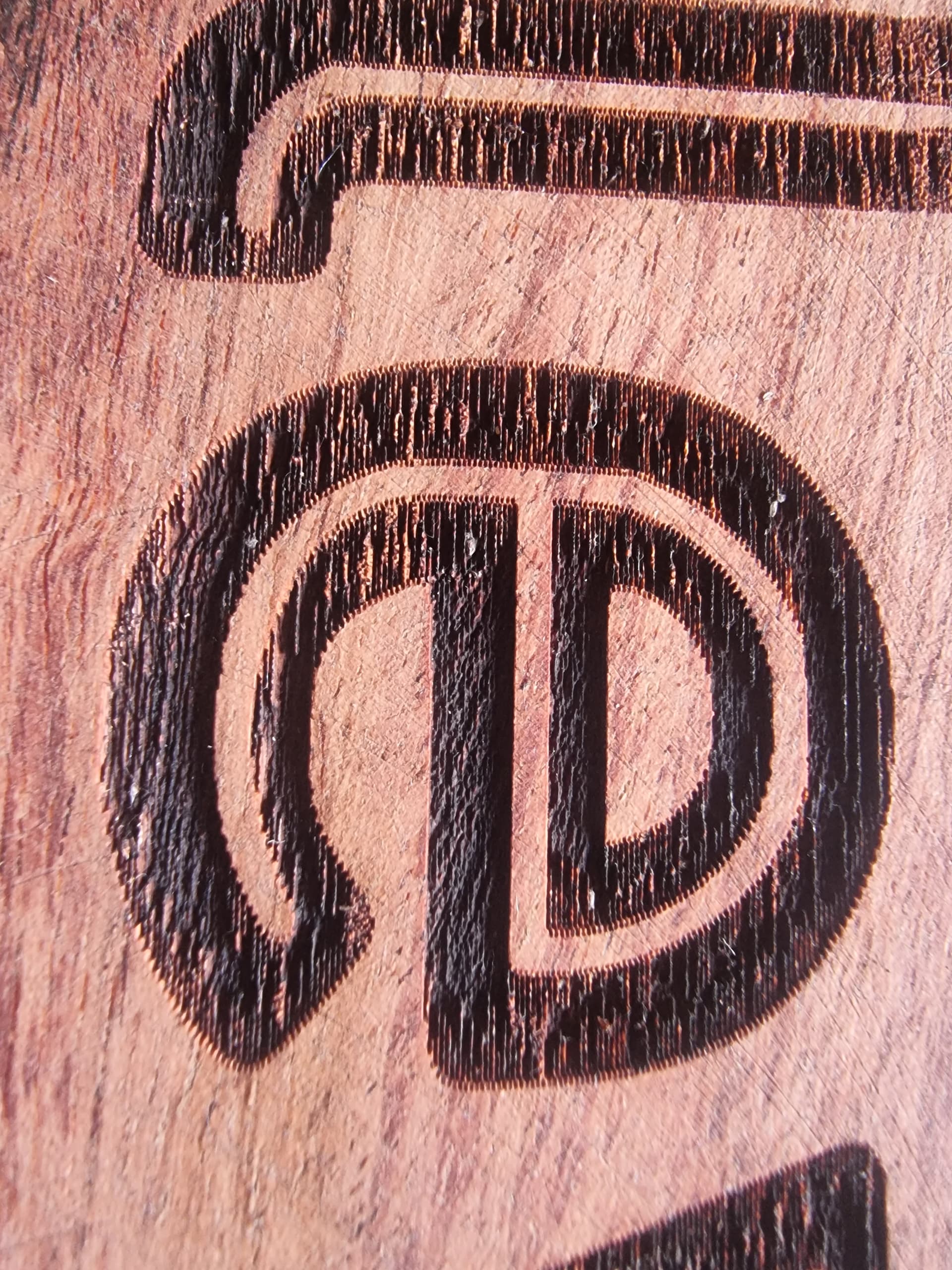
So, looking at the letter ‘E’ i can see highs and lows in the engraving. Definitely not smooth engraving…but then towards the bottom of the ‘e’ there is a perfect clean flat spot where it seemed to work fine. Bit on the outter edges its all jagged and rough. Any ideas
You burning interlaced, both directions. and your laser appeared to have a bit of delay.
You may burn one direction only - this interlacing will disappear.
Or reduce speed and power accordingly till delay become unnoticeable…
For LightBurn staff: you may implement time compensation for laser reaction/delay. Many lasers (solid state) have systematic delay. This become more obvious as more powerful solid state lasers available and speed increases. Compensation in software is doable and would be nice.
Are you aware of the Offset Scanning Adjustment available in Device Settings?
Scanning Offset Adjustment - LightBurn Software Documentation
PY,
Yep, this appeared it. This is just static offset.
I think time based would be more universal.
Ironically, I do not have LightBurn to be aware of it.
Not sure how you’re differentiating this but I believe the mechanism is in fact time based. From what I’ve seen the model extrapolates the timing adjustment for all cutting speeds based on a set of known offsets. The software then triggers the firing of the laser ahead of where it needs to cut based on the calculated response delay.
Does it matter? If method is efficient and produces necessary results - everybody happy.
But, if you wish to dig deeper: I have not seeing the code, but it appeared to me that there is no abstraction to timing. Speed is the argument and results from different speed measurements are offsets and interpolated for different speeds.
Would it be time based - single value would be necessary and no need for any interpolation.
But then there is a possibility that GRBL (G-code) protocol itself is time unpredictable. It is not time synchronous and time is not a parameter there. It is rather task and dimension based, so maybe dimensional method is more effective here.
Anyway, original question is answered.
(Me: I just burn exclusively one way, no need to mess with compensation. Laser timing can also be different for ON and OFF transitions. So even with best effort of alignment, the fact that burnt edge produced by ON vs. OFF transition may have some difference, some interlacing may still be present, hopefully very minor. )
Only if it was a matter of question but not otherwise.
No. Not directly other than as a component of speed.
I don’t think I understood you initially. So would this single dimension only define laser activation delay? If so, I can see that working for all speeds. However, I think the difficulty is in determining that delay. One obvious solution would be to setup a scope and some other electronics to capture the delay but most people won’t have access to that. Another could be to use some high speed camera to determine the delay.
My assumption is that the way the current model works is that it backs into that timing value. Whether this is a single value or multiple values I’m not sure.
Real-time is not guaranteed and there’s a buffer to contend with for response to immediate action. However, performance should be entirely predictable on a given hardware platform although I assume it would be non-trivial to generalize any guarantees across hardware.
This thread become overload to Nate’s question. But it is fun for us.
PY, That interlacing is single millisecond(s) scale. GRBL calculate trajectory on the fly. Machine specific settings like acceleration and max speed most likely are different for different machines. Even serial buffer delay will affect exact timing. And that is huge variable on different PCs. I can see my different computers filling buffer at different rate. I guess it is possible to dump GRBL settings and compensate for acceleration and speed, but then what is more practical. A the end maybe dimensional compensation is simpler/cleaner for GRBL machines, even with multiple sample points and interpolation.
As we are getting deeper: I have a variety of laser modules now, in each case see at high speed that accel-decel lead in and lead out portions are different for each one. There is also usually a tiny gap at the beginning. For M4 control GRBL supposed to compensate to keep energy per dot constant. The problem is that all lasers are not linear. They may integrate PWM into very linear voltage, but then laser itself is not linear. This maybe lesser problem for CO2 as their control is different. But for laser diode this is one big non-linearity. So there is a “min” “Spindle speed” (S=parameter, power for laser) and there is compilation time way to map non-linearity, but this is very cumbersome and created value is lesser than investment, and it is not switchable on the fly, required reflashing.
How it is related to timing: If I raise minimum S for given work - it takes less time to get to burning power, so that min S modulates response/delay time.
Running at more or less constant settings should not be a problem, so is at low speed,
Just thinking aloud. I just burn one way only. Don’t mind me. There are more ways.