Drawing a spiral/snail cam

Thanks. Yes I’m aware of all that. It just doesn’t lend itself as far as I can see to specifying an inner radius in anything other than % (no mm or other linear unit).

I’ve no doubt you could do it with a bit of fiddling but there are easier ways. Although Affinity Designer is very good value it still costs something. When trying to find a solution for someone else I always like to find a way using free software if possible.

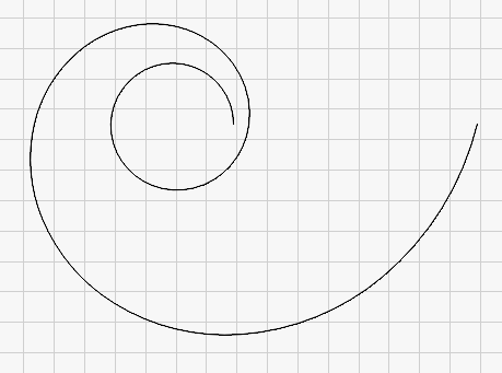
Here’s a better one.

This covers the full adjustment range but only over 270° rather than the full 360°. Obviously with the previous designs you wouldn’t be able to get right down to the minimum radius unless you added a narrow ‘follower’ to your fence.

1 Like

For the past couple of days I’ve been (re-)familiarising myself with B4J as well as learning a bit about SVG files. I’ve been working on an application that will generate a spiral in SVG format. I usually develop my apps in Lazarus but wanted this to be cross-platform because there are LB users running on Windows, MacOS, and Linux. Lazarus will create cross-platform apps but I don’t think it is very straightforward hence I’ve written this in B4J. I haven’t managed to work out the cross-platform stuff yet but you’ll find a link to a zip file containing the Windows executable and support files here. Just download it and unzip it somewhere convenient, there’s no installer at the moment but there might be in the future.

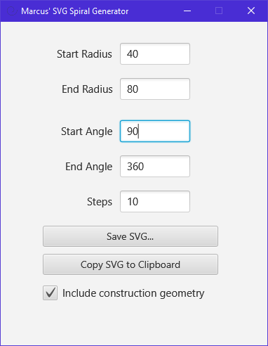
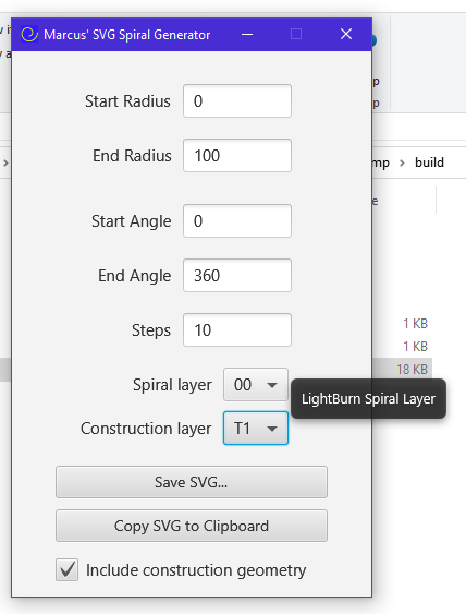
Here’s a screenshot:

image

I think the app should be fairly self-explanatory. It’s crude as far as error checking is concerned - i.e. there isn’t much right now, but as long as you put sensible values in you should get sensible results. The curve that’s generated uses circular arcs to approximate a proper spline as from what I’ve read it’s pretty complicated to do the latter. I might revisit that at a later date if I’m looking for something to do! The arc based curve should be good enough for most purposes.

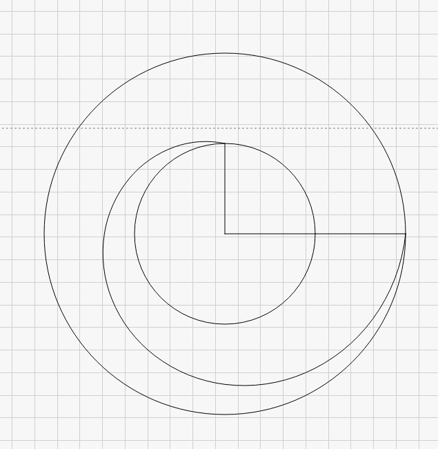
The image checkbox when checked will also draw two circles representing the min and max radii as well as lines from each endpoint back to the centre. I’ve included this as it makes it easier to find the centre once imported or pasted into LB (or any other app you potentially use it with).

You can save the SVG to a file or you can copy it to the clipboard where you can paste it directly into LB without having to save & import an SVG file.

I plan on making some improvements but I just wanted to get something usable out there as quickly as I could.

Hopefully @stixstudios will find this more convenient than using FreeCAD, and others will find it useful as well. If you have any problems with it just let me know.

Hope you find it useful.

3 Likes

I hadn’t heard of B4J but the term RAD and Lazarus are wild blasts from the past. Thank you for the nostalgia ride and offering a tool for the community. Very cool.

3 Likes

Thanks, I hope people find it useful.

Edit:
I’ve no doubt that LB will have its own spiral tool sometime in the future and I expect the LB developers will be able to code it a lot quicker than I did!

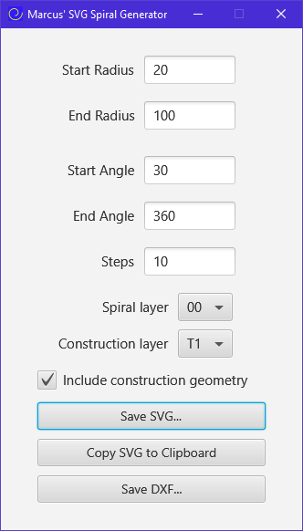
I’ve updated my spiral generator app with a few improvements:

  • Settings are now remembered between sessions

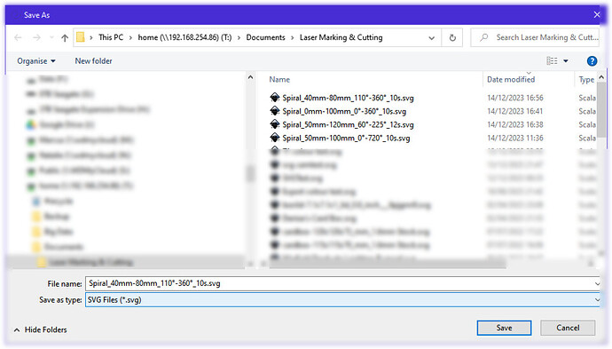
  • The folder that you last saved an SVG to is remembered between sessions and the filename is automatically generated:

So, nothing major but an improvement over the initial version. I am considering adding the option for the user to individually select the LB layers for the main profile and the construction geometry. I don’t know whether that is something that people would want as it’s easy enough to do once imported into LB.

The same link that was posted above should work for the updated version.

2 Likes

Ok, another update: I’ve added the option I mentioned in my last post to allow the user to set the layers for the spiral and the construction geometry.

If you have any problems with it just let me know.

Hope you find it useful.

2 Likes

Fan-bloody-tastic Markus. Wow!

I gotta laugh about it. Here was me initially asking “I don’t really need someone to draw it for me” and you have created a stand-alone application!!! F*ck!!!

So I downloaded the software and used it to create the basis for the artwork that I needed.

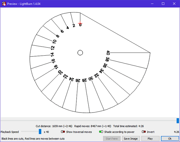
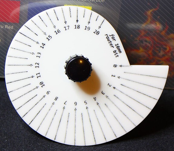
I cut it out today. The increments are 0.5mm. The whole thing is around 85mm wide. The engraving does look like crap because I just coloured it in with a marker and wiped it off. No biggun because the main important increment parts are there - and measure correctly when tested.

Next step is to install this in place. A bit tricky, but easily done.

Cheers, thanks Markus.

[EDIT] As a matter of interest, I made the difference between the inner and outer diameter to be 24mm. That way it can be easily divided into 360 to determine the correct angle of each whole increment (15 degrees = 1mm in this case).

1 Like

Great, I’m glad it worked and you found it useful. Hopefully you found it easy to use as well.

My go to for vector drawing (laser, 3d or very high res prints) is Affinity Designer. It has a very useful Spiral drawing tool. So does Inkscape, the awesome freeware. But Designer has PC, Mac and IOS versions, all cheap - like me.

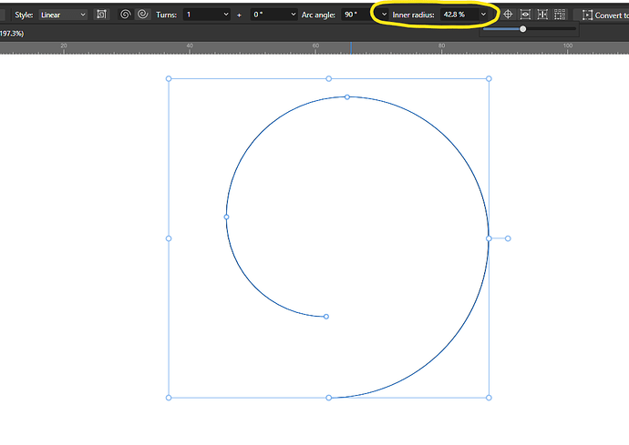
Yes, I’m an Affinity (as well as CorelDraw and very occasionally Inkscape) user too but as I pointed out in an earlier post it’s not exactly easy to produce a spiral to exact dimensions like the OP wanted. Affinity, Inkscape, CorelDraw, (and maybe Illustrator?) can do ‘arty’ spirals but not if you want something to very specific dimensions. The spiral tool in Affinity will only do full revolutions, and the inner radius can only be set as a percentage of the overall size, making it very difficult. If you know different it would be great if you could show us how it is done.

Here’s a further update… it now has DXF output as well.

FYI: One issue with the DXF format is that colours are not specified as RGB but instead uses a fixed palette (undoubtedly because ACAD is the same). Unfortunately the DXF palette doesn’t have colours that exactly match all of the LB layer colours. You can check this out by exporting a DXF file from LB and re-import it, you’ll find some of the objects will come through on a different layer to the original. I tried to find closest matches between the LB and DXF palettes but couldn’t find a good 1:1 mapping so I just followed LB’s lead and used the same ones.

I’ve tested the DXF with a number of different applications and some import perfectly while others either bring it in at some odd size or throw an error. There’s no problem with LB (apart from the aforementioned unavoidable* layer colour issue) so most users shouldn’t have a problem.

*I say unavoidable… if LB were to change the layer palette to match the DXF one (well a subset thereof) we could get perfect round-trip export & import of DXF. I’m not expecting LB to do this but it would get rid of this little annoyance).

Anyway, I hope you find this addition useful.

1 Like

Apologies, I introduced a small bug into the last version. It was failing to draw the circle representing the end radius so that’s now been fixed.

EDIT:
The forum won’t allow me to submit more than three posts in succession so I’ve got to tack it onto this one.

Another update!

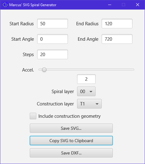
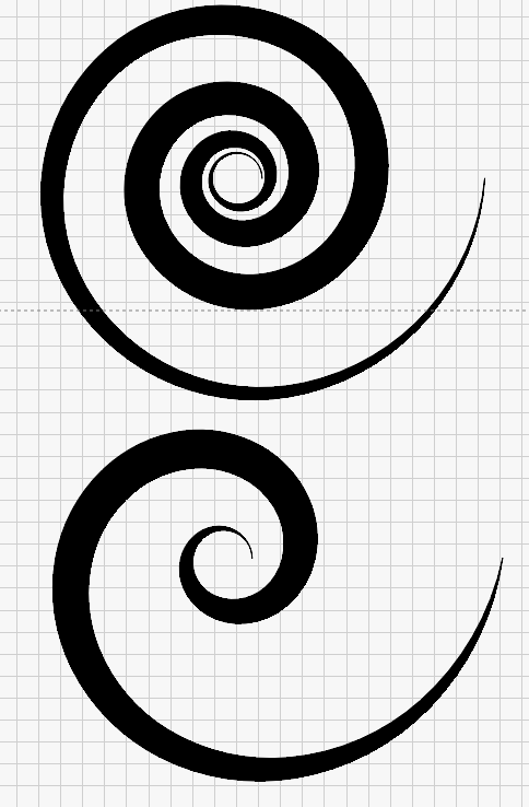
I’ve changed the layout a bit and added an ‘accelerator’ slider to create non-archimedian spirals. With this you can create spirals like this:

image

If you create a couple of spirals with different ‘accel’ values then join them in LB you can create effects like this:

If you want the standard ‘constant growth’ spiral just set the slider to ‘1’.

Hope you like the addition.

With a few more tweaks you’ll finally be able to recreate the Debian swirl. :wink:

image

1 Like

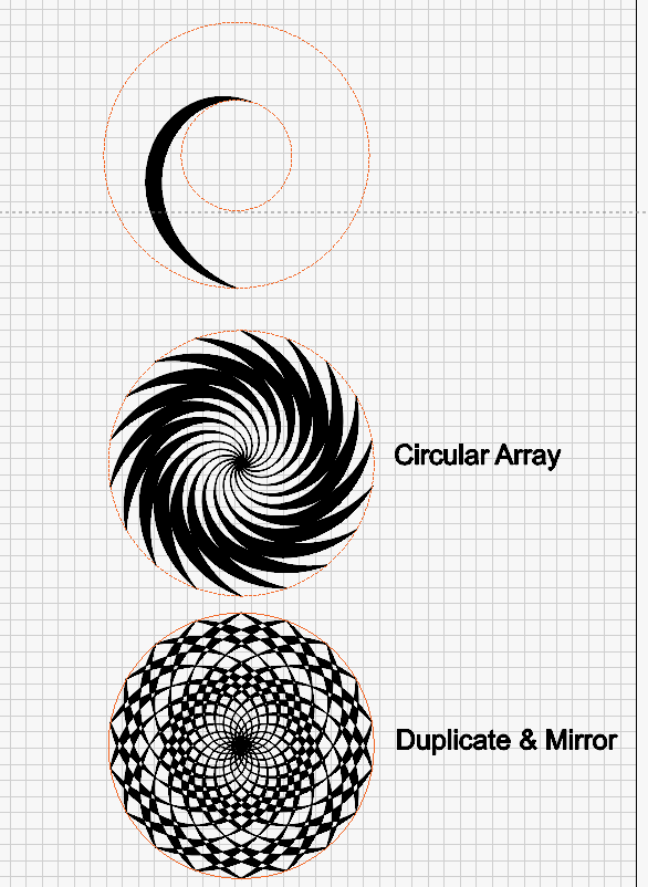
Or something like this:

1 Like

In software programming, this is what you call “scope creep”. :laughing: :crazy_face: :+1:

For context, I’ve been there. I’ve dabbled in creating many and varied software solutions over the years. The last one was using Xojo.

I can’t remember what the name is for when you make an “improvement” to the software, only to find that it screws up another part that was previously working quite well as it was. There is a proper name for it - just can’t remember it right now, but not important.

Anyway Markus, I downloaded your original version that includes the construction lines, and that’s all that I needed. That’s how I created the final artwork that I used. Many thanks for that.

It was a bit of a pain to get what I wanted. Not because of your software solution, but because I’m using an old 2013 iMac as my main “house” computer.

I had to use a usb stick to copy the software to an old laptop running Win8 and it worked perfectly - no requirement to install any DLL’s etc. But I couldn’t do any extensive testing on the w8 machine because I don’t have any appropriate software on it to test it with.

So, it was copying back to a usb drive, back onto the Mac, making some adjustments in illustrator. Then copying that back to the usb drive to upload on my Win7 machine in my garage, which is my main machine that has LB on it - which is connected to my laser cutter.!!! Heck!, I need to sort out my networking issues. :upside_down_face:

Final adjustments were done in LB, then cut. The end result was perfect - except for my rather rudimentary job of colouring in the engraved parts. I’ve since engraved/etched/cut another one that should help it “look” nicer, but as it is, it’s fine.

Your software did EXACTLY what was required. I didn’t (and couldn’t) test it under various circumstances. I didn’t bother to fool around with options. I simply just input the start and end radius, saved it, and it was done.

The only thing that I thought was strange was when I imported the SVG into Illustrator, it was not at the correct size that I determined in the software. It was much smaller. Can’t remember exactly, but I still have the original if you want to know.

In any case, I simply enlarged the graphic element to the correct size that I needed and it worked as expected.

Thank you so much Markus. Great job, it saved me many hours of trying to come up with a solution myself. :+1: :+1: :+1:

Cheers, Steve.

[EDIT] for over-use of the word “need/needed”.
Yes, tell me about it! Also known as “feature creep”.

I’ve developed various applications too, for myself and for use by the engineering companies I’ve worked at. I started programming back in the early '80’s on my BBC Model B in basic and assembler, and have since used VB v1-v3, C & C++, Turbo Pascal, Delphi v1-v7, B4A, and B4J (but very little in B4J).

EDIT: And how could I forget Lazarus?!

I’ve not heard of that one but I’ll take a look. I see it does cross-platform which looks interesting.

Yes, I’m not surprised. SVG uses pixels as its unit and the application that’s importing it has its own way of determining the DPI. The most common standards are 72 & 96 DPI. When I was creating the app I was fully expecting to have to apply a scaling factor to the input sizes to get an output that was at the correct scale in LB. However, this wasn’t the case. If you look at the generated SVG in a text editor you’ll see that the coordinates match the input dimensions. Somehow LB interprets this as mm. Unfortunately other applications don’t, and as I think I mentioned in an earlier post it comes in at various sizes! That’s the main reason for adding the DXF (but that seems to have its own issues!).

No problem, you’re welcome. (That’s Marcus with a ‘C’ by the way :wink:)

Whoops! sorry about that “Marcus”. Anyway it’s 1.20am here and time to retire for the evening. When I get the cam installed I’ll post an image of it in-situ.

I guess I didn’t really need a cam. I could have just used some segmented wheel thing. But using a cam in this way, is a rather elegant solution to a simple problem - I think.

Thanks for helping me sort it out. Cheers.

[EDIT] Also, if others get some benefit out of this thread, then that is a bonus :+1:

:+1: Goodnight, sweet dreams!

super cool , smart , and kind - thank you!

1 Like