Final test of upgraded K40: Importance of focusing the beam

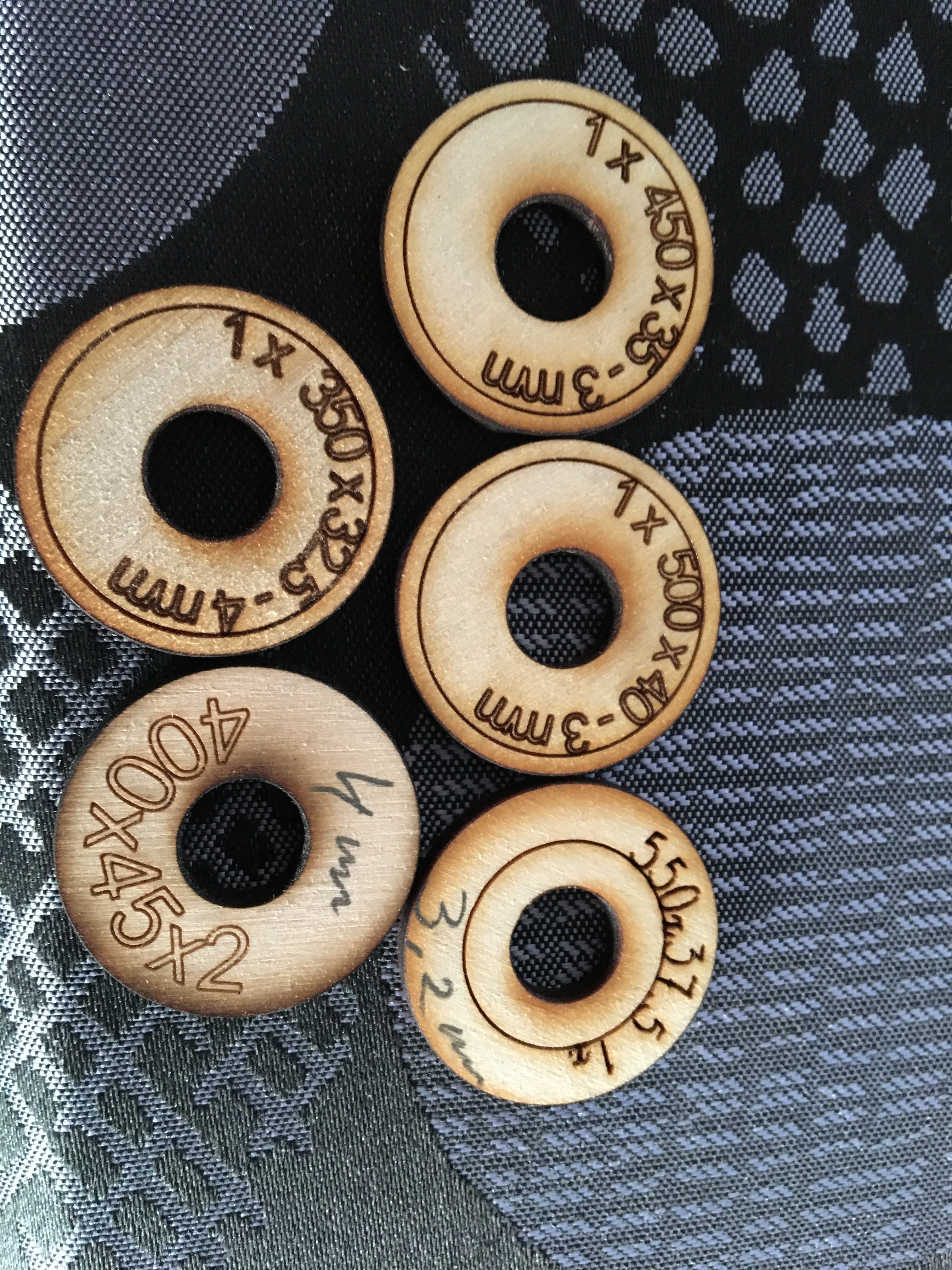
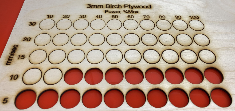
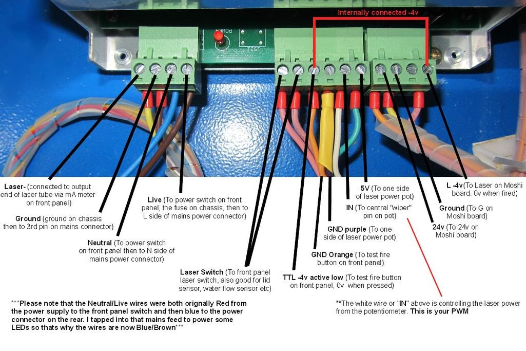
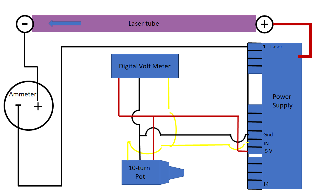
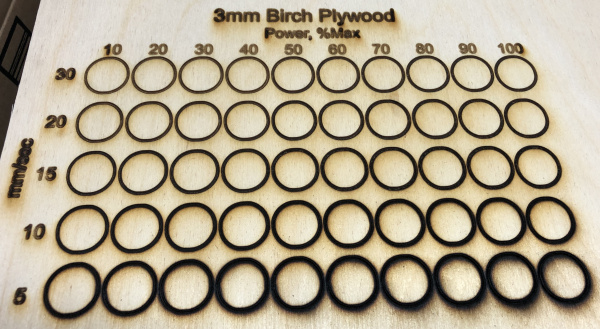
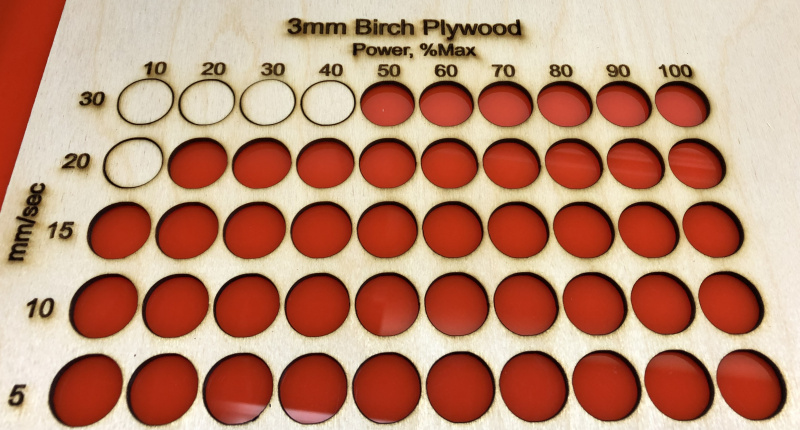
I’ve had my K40 for about 6 months and have spent most of that time upgrading it. I’ve replaced the original firmware board with Cohesion3D LaserBoard (now running with Lightburn), increased the bed size to 12x20 inches with a new gantry, added a scissors lift with stepper motor to adjust Z height (mostly untested at this point), replaced original laser head with one from LightObject and lens from Cloudray, added an air-assist pump, replaced digital control panel with analog ammeter and 10-turn potentiometer and pushbutton switches for laser test and control of smoke/fumes exhaust system. In other words, about the only parts of the original K40 I kept were the case and the CO2 tube. After getting the new gantry to move properly and accurately and aligning the laser beam, I decided to cut something out of 3mm birch plywood. I ran a test speed/power grid and here are the results:

image

The higher speeds looked OK, so I ran this image as a test:

image
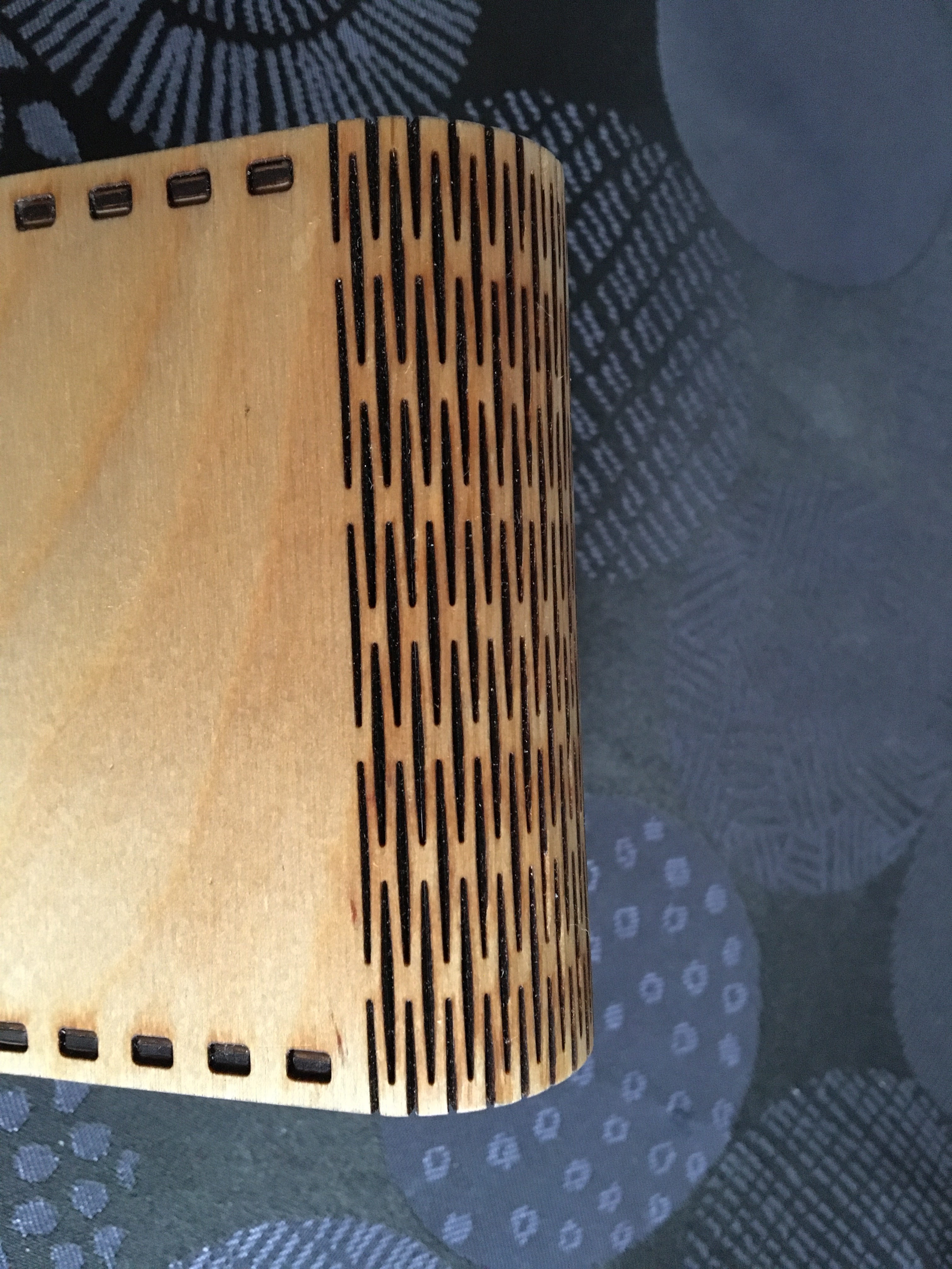
I thought it would be a good test because of all the small holes. My first attempt came out like this:

Ooops! Then, I remembered I forgot to focus the beam with the new head and lens. I also needed to fix the plywood to the bed better so it wouldn’t move.

After focusing, I ran the test speed/power grid again with these results:

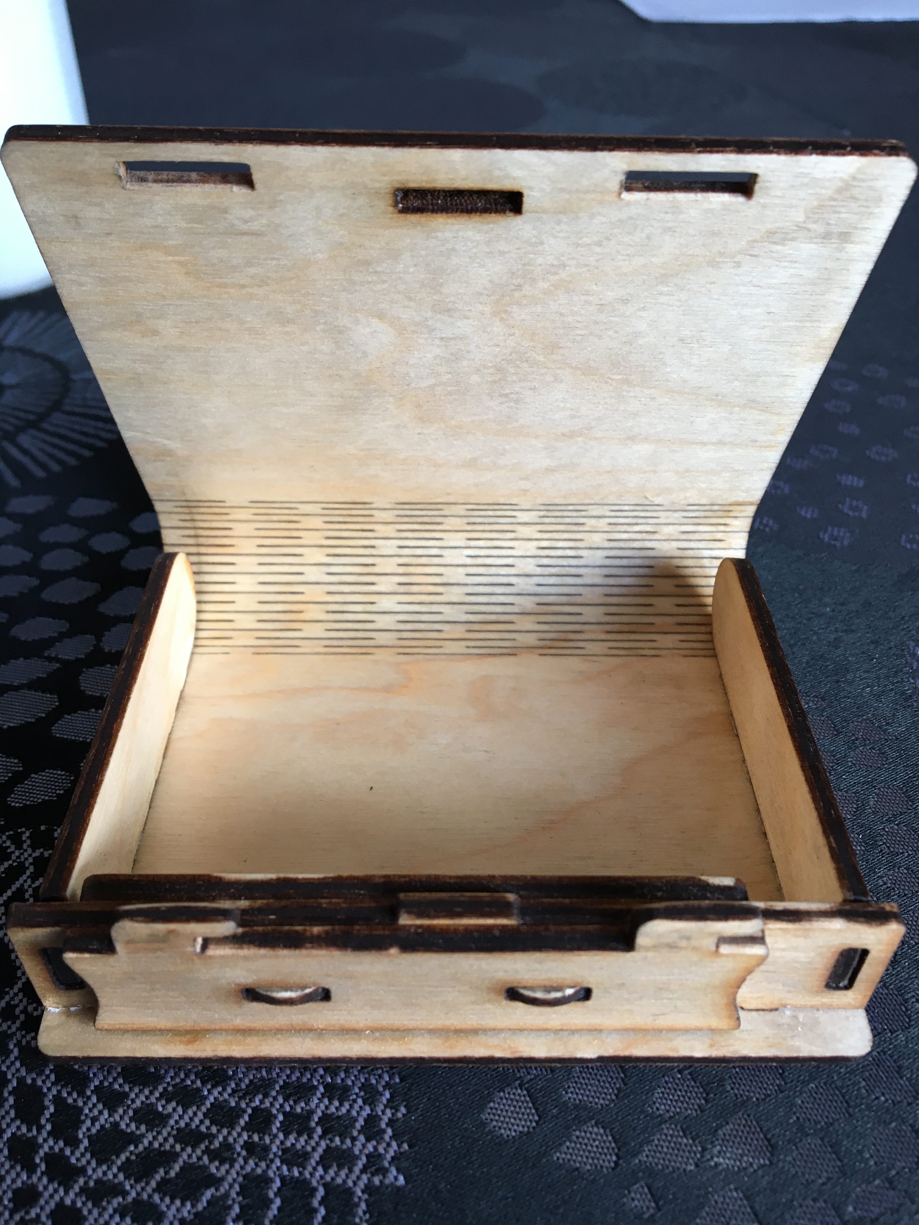
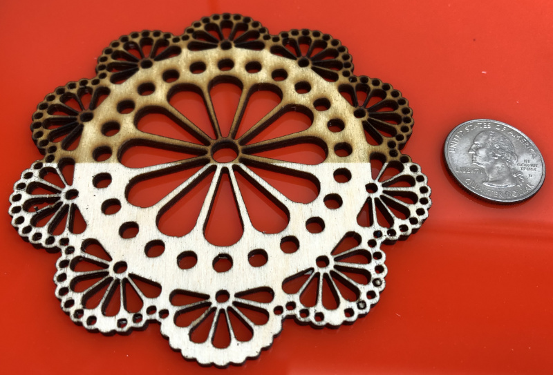
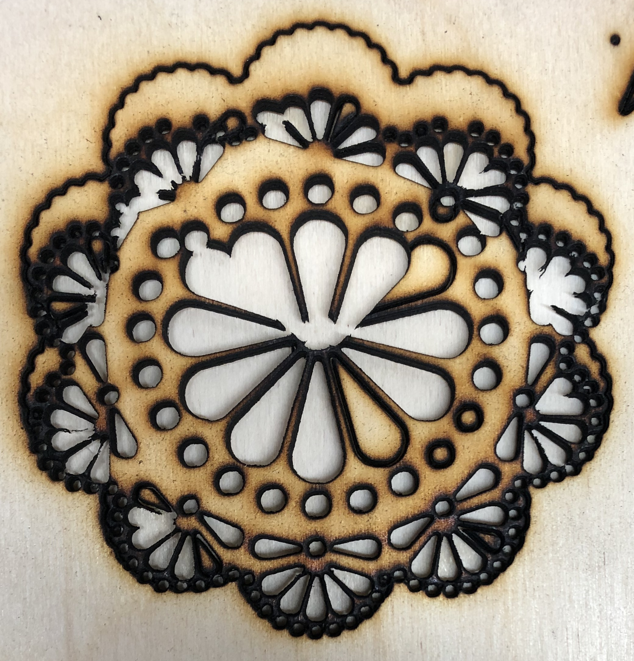
Much better results so I gave the image a second try:

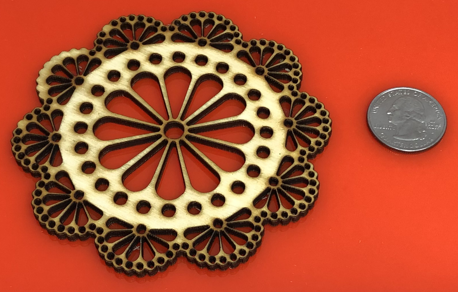
I’m very pleased with this result. I chose 30mm/sec, 50% power set in Lightburn (input voltage=2.7 which gave 15mA at 100% power) and 3 passes to cut this image. There are a few small holes missing in the upper-left side of the coaster, but it turns out those holes are missing in the image for some reason…I don’t know what happened to them. I think my next test will be with painters’ tape covering the surface to reduce/eliminate charring on the surface.

Anyhow, this was a big lesson for me on the importance of focusing the beam. After several months of messing around with the machine, I think I’m finally ready to start cutting.

1 Like

Hi DB,
Congratulations on your new setup. I am interested in the extension you have made, a few pictures from the project will be appreciated.
Your point, finding the right focal spot, is in my experience, also the most important thing you can do to achieve a good result. I always spend a lot of time on it and although I make small test pieces and save them, it is often a little different next time.

Your power / speed test is in my opinion a little too rough.
Either your playwood is a poor quality or something else is wrong with your final test. With a good quality playwood (3mm) I cut with approx. 500 mm / min at 35-40% (10.5-12 mA) in a single pass.
With good quality I mean only the opportunity to cut it easily with a laser. There are lots of kinds of playwood, it’s often just like a lottery, to grab the right material.

(3mm playwood)

Thanks for your interest. I realize now, based on your input, that I made a logical error in running the test speed/power grids. After the first run, none of the circles were cut out with 2 passes. I, then, re-focused the beam and increased the number of passes to 3, forgetting that the poorly focused lens was the probable reason for the reduced efficiency of the beam in the first test. As you can see in the second test, almost all the circles were cut out. I will re-run that test with just 1 pass to see what happens. I will note that your speed of 500mm/min ≅ 8mm/sec so my speed ranges of 5 and 10 mm/sec should bracket yours.

By “extensions” I assume you mean the enlarged bed??? If not, maybe you can clarify? In either case, I wasn’t very accurate in my original description. My primary goal for the enlarged bed was to be able to use 12"x12" (305mmx305mm) materials for cutting. I met that goal; however, the actual cutting area of the new bed is 12.2" (335mm) wide, but only 9.85" (250mm) tall. I will post some pictures with additional details later today of the various modifications I made.

Hi DB,
Yes, that is enlarge of the work area I meant. Google Translate is really fine but not perfect, yet :wink:
It’s not much you get out of your work and money if you only get 335mm x 250mm, I think.
I threw out the original table and made a new one with 4 screws and a hole plate. In fact, I made 3 pieces of different heights but fine-tune them individually. But in practice, it turns out that I rarely change and just use spacers of different heights for the different thicknesses. My bed is 320 mm x 230 mm and I have sometimes wanted a bigger machine and am a little tired of cutting all the “small” wooden boards.

When you run the test again at smaller power and speed intervals, you will surely find the most correct / effective combination, (only with a single pass!)
… before I forget it, sometimes impurities on the mirror or lens also give a wrong result of the focus, be aware of that too.

Yeah, I was pretty disappointed with the final height of the work area. I may be able to enlarge it a little by changing the location of one of the stepper motors, but I doubt I’ll ever get to a full 12" assuming I stay within the original case.

I re-ran the speed/%Power test using just 1 pass with the following result:


This result confirms the setting you suggested. I chose 10mm/sec and 50% power (resulting in 12mA) for another test cut of the intricate coaster. I tried covering half of the wood to be cut with blue painters’ tape to see how it did with reducing or eliminating burn marks. Here’s how it looked after the cut:


And, then, after removing all the tape:

The tape did a nice job of eliminating surface burning.

Lastly, here are some other photos of my upgraded K40 and a video of the scissor platform Z-table.


I haven’t completed the wiring to all the buttons yet. Right now, only the bottom-left 3 buttons work to control the exhaust system (2 fans) and air-assist pump and the momentary button below the ammeter for test-firing the laser. The digital readout and 10-turn pot right of the ammeter are working. Once all the wiring is complete, I’ll make labels for all the components. I cut (CNC) the control panel from 0.1" aluminum.


It’s a rat’s nest of wires inside-right of the case. I gained some space for the X-axis by turning the power supply on its side. Once I’ve got all the wiring done, I’ll spiral-wrap all the wires.


These are the new outlets on the back next to the power input. Power to them is controlled by some of the pushbutton switches on the front control panel. Right now, they power the air-assist pump and the 2 fans for the exhaust system.


This is the scissor platform I hope to use to adjust the height of the z-table. I plan to attach a 12"x12" aluminum plate to the top. The plate will have a bunch of these:

https://www.amazon.com/gp/product/B00UOXGR14/ref=ppx_yo_dt_b_asin_title_o06_s00?ie=UTF8&psc=1

spaced about 15 cm apart to support the material being cut.

Here’s a link to a video showing the Z-table in action:

Congratulations on the huge step forward. Your coaster looks a lot better now.
There are two things that confuse me. I’m not the big electrician so I ask. Do you use the potentiometer on the panel to set power with? and not the internal one from LB? You write 50% gives you 12 mA, then what is your max power (100%) from the test template in mA?
You could send both test files and I would “test” them with my setup.

I’m not the big fan of scissor platforms Z-tables, for my needs they are not big and stable enough. I work mostly with 3 and 4mm material, I only replace the support rails in the sides, under the work pieces, quickly and simply.

Maybe I just haven’t read or understood it all right, so it’s extremely nice that we have this forum to exchange our experience and help each other.

You might want to consider using a steel plate rather than aluminum. Aluminum is highly reflective whereas mild steel is much less so.

1 Like

I’m a little concerned with the weight of steel. Maybe there’s something I can do to the aluminum to reduce reflectivity???

Maybe stainless steel with a brushed finish???

Maybe a thin steel sheet “veneer” on 3mm plywood. That would probably be lighter then the aluminum plate I currently plan to use. Thanks for getting me thinking about this.

1/8" mild steel is 5.1 lbs per sq ft.
1/4" aluminum is 3.528 lbs per sq ft.

I am comparing 1/8 steel to 1/4 aluminum because aluminum is (mathematically) ~1/3 the stiffness of steel. Typically, for equivalent stiffness, aluminum needs to be 44 percent thicker than the steel. Therefore, 3/16" aluminum would be about right (again, mathematically), but 3/16" aluminum is pretty flimsy compared to 1/4" aluminum plate.

Just a suggestion.

Maybe there’s something I can do to the aluminum to reduce reflectivity???

You could have the aluminum shot blasted and anodized but I would guess that would be pretty expensive.

I would worry about the plywood warping - what you need is a consistently flat surface.

I appreciate all the input you’ve provided!

1 Like

Aluminum is at least as reflective to the CO2 laser as steel. Same for most other metals, which is part of the reason we cannot do much more than remove anodize coating, As far as I know, the only ways to reduce reflections are to absorb it or diffuse it.

One thing to note related to this discussion is the fact that the material to be cut will be sitting on top of these:

https://www.amazon.com/gp/product/B00UOXGR14/ref=ppx_yo_dt_b_asin_title_o06_s00?ie=UTF8&psc=1

that are attached to the top surface of the plate (aluminum or otherwise). Being 9.5mm tall, the beam will be rather unfocused by then before whatever reflection will take place.

Nice work!

I am curious if you can detail the specifics of how you wired the 10-turn pot into the mix.
I am looking to do the same thing, so that I can set the max output voltage with the pot to 18ma for my tube.
That way I can use 100% in Lightburn power settings instead of the 55% I am using now.

I did get those spikes (in black) and they work well. Of course the bed needs to be adjusted for focus.

I used this ammeter:

with this 10-turn pot:

https://www.amazon.com/gp/product/B07D82DD79/ref=ppx_yo_dt_b_search_asin_title?ie=UTF8&psc=1

and this digital volt meter:

https://www.amazon.com/gp/product/B07B4D9MWQ/ref=ppx_yo_dt_b_search_asin_image?ie=UTF8&psc=1

The basic idea is to put the ammeter in between the cathode (-) negative end (the light-emission end) of the CO2 laser tube and the power supply (left-most terminal labeled “Laser” in the photo below) using the existing black wire. The power supply in my K40 looks like this with 14 positions 1-14 starting from the left.

Here’s a drawing of how everything’s connected:

Now that I’ve got this working, I use the pot to set the voltage to the laser tube so I get 15-18mA on the ammeter. Then, I use Lightburn to set the various percentages.

1 Like

Excellent detail, thank you so much!

I will see if I can get this working over the weekend :smiley: