Good luck! Of course, be very careful. I always completely unplugged everything from the wall 120V when working with the machine.
Here is a bit more information that may help:
A very helpful diagram provided by “jimbydude” here:
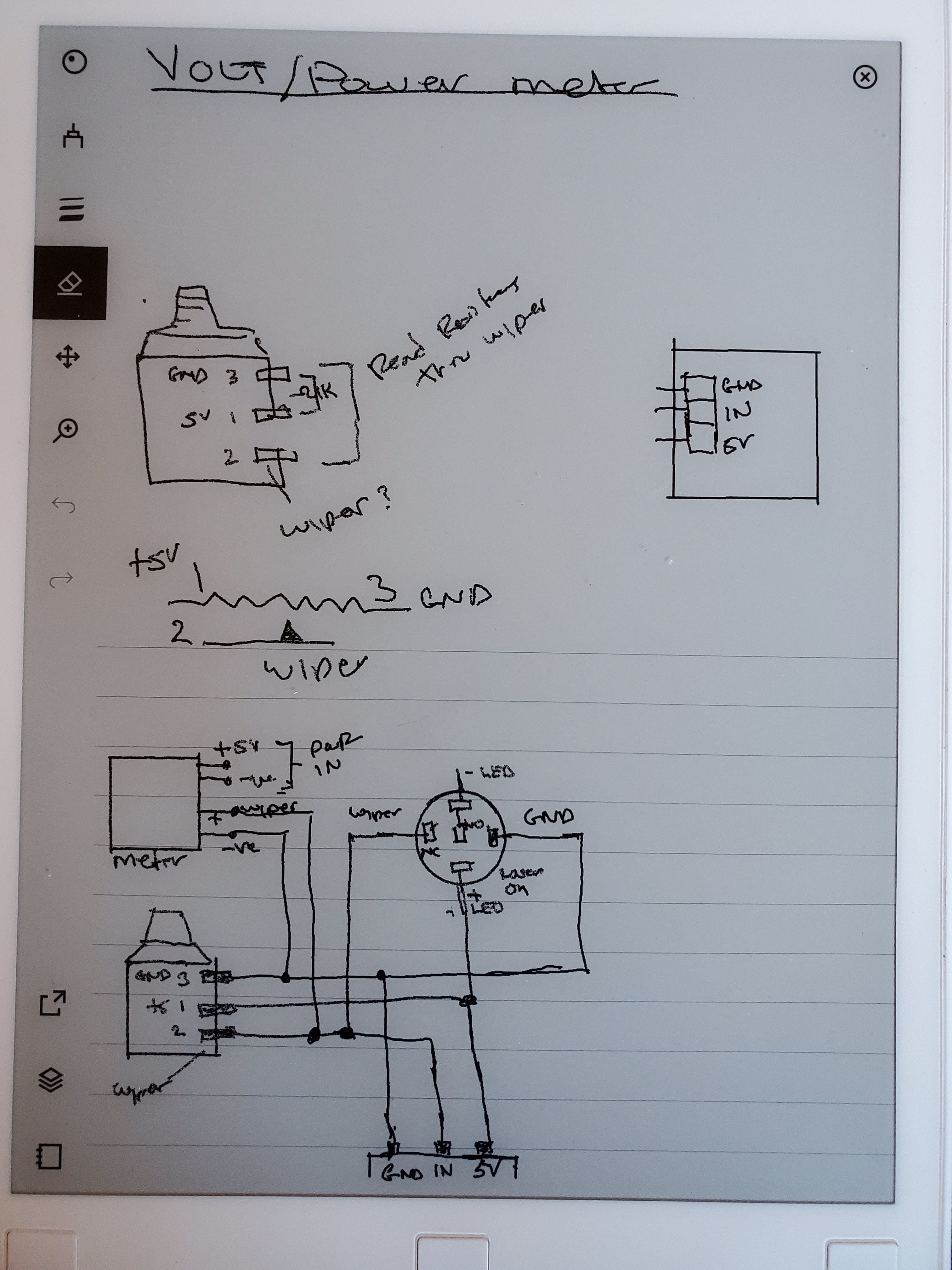
I omitted the momentary pushbutton switch from the circuit depicting the voltmeter and ammeter which made the wiring much simpler. Other comments by “jimbydude” there were most helpful.
Could yo post your Cohesion setup file? I’m just wondering what a successful cohesion board setup looks like.
My original board fires the laser just fine, but no matter how I setup my Cohesion board, the LED showing the laser is firing, just blinks super fast and no cutting or engraving happens. No combination of the panel settings or LightBurn power settings make any difference. It all appears to working and signalling, but no power, or not enough power, is applied to the laser.
I’ve pasted the config.txt file for my LaserBoard below. I believe the only changes I’ve made are the alpha_, beta_ and gamma_steps_per_mm values to calibrate my stepper motors. If you want to start from the original firmware, check out this discussion"
=================================================================
#Cohesion3D LaserBoard v0.2
NOTE Lines must not exceed 132 characters
Robot module configurations : general handling of movement G-codes and slicing into moves
default_feed_rate 4000 # Default rate ( mm/minute ) for G1/G2/G3 moves
default_seek_rate 24000 # Default rate ( mm/minute ) for G0 moves
mm_per_arc_segment 0.0 # Fixed length for line segments that divide arcs 0 to disable
mm_max_arc_error 0.01 # The maximum error for line segments that divide arcs 0 to disable
# note it is invalid for both the above be 0
# if both are used, will use largest segment length based on radius
#mm_per_line_segment 5 # Lines can be cut into segments ( not usefull with cartesian
# coordinates robots ).
Arm solution configuration : Cartesian robot. Translates mm positions into stepper positions
alpha_steps_per_mm 100.325 # Steps per mm for alpha stepper
beta_steps_per_mm 99.9841375 # Steps per mm for beta stepper
gamma_steps_per_mm 3234 # Steps per mm for gamma stepper (was 316.9)
Planner module configuration : Look-ahead and acceleration configuration
planner_queue_size 32 # DO NOT CHANGE THIS UNLESS YOU KNOW EXACTLY WHAT YOU ARE DOING
acceleration 2500 # Acceleration in mm/second/second.
#z_acceleration 500 # Acceleration for Z only moves in mm/s^2, 0 uses acceleration which is the default. DO NOT SET ON A DELTA
junction_deviation 0.05 # Similar to the old “max_jerk”, in millimeters,
# see https://github.com/grbl/grbl/blob/master/planner.c
# and https://github.com/grbl/grbl/wiki/Configuring-Grbl-v0.8
# Lower values mean being more careful, higher values means being
# faster and have more jerk
#z_junction_deviation 0.0 # for Z only moves, -1 uses junction_deviation, zero disables junction_deviation on z moves DO NOT SET ON A DELTA
#minimum_planner_speed 0.0 # sets the minimum planner speed in mm/sec
Stepper module configuration
microseconds_per_step_pulse 2 # Duration of step pulses to stepper drivers, in microseconds
base_stepping_frequency 100000 # Base frequency for stepping
Cartesian axis speed limits
x_axis_max_speed 24000 # mm/min
y_axis_max_speed 24000 # mm/min
z_axis_max_speed 24000 # mm/min
Stepper module pins ( ports, and pin numbers, appending “!” to the number will invert a pin )
alpha_step_pin 2.0 # Pin for alpha stepper step signal
alpha_dir_pin 0.5 # Pin for alpha stepper direction
alpha_en_pin 0.4 # Pin for alpha enable pin
alpha_current 1.7 # X stepper motor current
alpha_max_rate 24000.0 # mm/min
alpha_acceleration 2500 # mm/sec²
beta_step_pin 2.1 # Pin for beta stepper step signal
beta_dir_pin 0.11 # Pin for beta stepper direction
beta_en_pin 0.10 # Pin for beta enable
beta_current 1.7 # Y stepper motor current
beta_max_rate 24000.0 # mm/min
beta_acceleration 2500 # mm/sec²
gamma_step_pin 2.2 # Pin for gamma stepper step signal
gamma_dir_pin 0.20! # Pin for gamma stepper direction
gamma_en_pin 0.19 # Pin for gamma enable
gamma_current 1.0 # Z stepper motor current
gamma_max_rate 24000.0 # mm/min
gamma_acceleration 2500 # mm/sec²
A axis
delta_steps_per_mm 157.5 # may be steps per degree for example
delta_step_pin 2.3 # Pin for delta stepper step signal
delta_dir_pin 0.22 # Pin for delta stepper direction
delta_en_pin 0.21 # Pin for delta enable
delta_current 0.6 # Z stepper motor current
delta_max_rate 12000 # mm/min
delta_acceleration 1000 # mm/sec²
B axis
epsilon_steps_per_mm 100 # may be steps per degree for example
epsilon_step_pin xx # Pin for delta stepper step signal
epsilon_dir_pin xx # Pin for delta stepper direction
epsilon_en_pin xx # Pin for delta enable
epsilon_current 1.5 # Z stepper motor current
epsilon_max_rate 300.0 # mm/min
epsilon_acceleration 500.0 # mm/sec²
C axis
zeta_steps_per_mm 100 # may be steps per degree for example
zeta_step_pin xx # Pin for delta stepper step signal
zeta_dir_pin xx # Pin for delta stepper direction
zeta_en_pin xx # Pin for delta enable
zeta_current 1.5 # Z stepper motor current
zeta_max_rate 300.0 # mm/min
zeta_acceleration 500.0 # mm/sec²
System configuration
Serial communications configuration ( baud rate defaults to 9600 if undefined )
uart0.baud_rate 115200 # Baud rate for the default hardware serial port
second_usb_serial_enable false # This enables a second usb serial port (to have both pronterface
# and a terminal connected)
#leds_disable true # disable using leds after config loaded
#play_led_disable true # disable the play led
Kill button (used to be called pause) maybe assigned to a different pin, set to the onboard pin by default
kill_button_enable true # set to true to enable a kill button
kill_button_pin 2.12 # kill button pin. default is same as pause button 2.12 (2.11 is another good choice)
#msd_disable false # disable the MSD (USB SDCARD) when set to true (needs special binary)
#dfu_enable false # for linux developers, set to true to enable DFU
#watchdog_timeout 10 # watchdog timeout in seconds, default is 10, set to 0 to disable the watchdog
Only needed on a smoothieboard
currentcontrol_module_enable true #
Extruder module configuration
extruder.hotend.enable false # Whether to activate the extruder module at all. All configuration is ignored if false
extruder.hotend.steps_per_mm 157.575 # Steps per mm for extruder stepper
extruder.hotend.default_feed_rate 60000 # Default rate ( mm/minute ) for moves where only the extruder moves
extruder.hotend.acceleration 3000 # Acceleration for the stepper motor mm/sec?
extruder.hotend.max_speed 1000 # mm/s
extruder.hotend.step_pin 2.3 # Pin for extruder step signal
extruder.hotend.dir_pin 0.22 # Pin for extruder dir signal
extruder.hotend.en_pin 0.21 # Pin for extruder enable signal
extruder offset
#extruder.hotend.x_offset 0 # x offset from origin in mm
#extruder.hotend.y_offset 0 # y offset from origin in mm
#extruder.hotend.z_offset 0 # z offset from origin in mm
firmware retract settings when using G10/G11, these are the defaults if not defined, must be defined for each extruder if not using the defaults
#extruder.hotend.retract_length 3 # retract length in mm
#extruder.hotend.retract_feedrate 45 # retract feedrate in mm/sec
#extruder.hotend.retract_recover_length 0 # additional length for recover
#extruder.hotend.retract_recover_feedrate 8 # recover feedrate in mm/sec (should be less than retract feedrate)
#extruder.hotend.retract_zlift_length 0 # zlift on retract in mm, 0 disables
#extruder.hotend.retract_zlift_feedrate 6000 # zlift feedrate in mm/min (Note mm/min NOT mm/sec)
#delta_current 1.8 # First extruder stepper motor current
Second extruder module configuration
#extruder.hotend2.enable true # Whether to activate the extruder module at all. All configuration is ignored if false
#extruder.hotend2.steps_per_mm 140 # Steps per mm for extruder stepper
#extruder.hotend2.default_feed_rate 600 # Default rate ( mm/minute ) for moves where only the extruder moves
#extruder.hotend2.acceleration 500 # Acceleration for the stepper motor, as of 0.6, arbitrary ratio
#extruder.hotend2.max_speed 50 # mm/s
#extruder.hotend2.step_pin 2.8 # Pin for extruder step signal
#extruder.hotend2.dir_pin 2.13 # Pin for extruder dir signal
#extruder.hotend2.en_pin 4.29 # Pin for extruder enable signal
#extruder.hotend2.x_offset 0 # x offset from origin in mm
#extruder.hotend2.y_offset 25.0 # y offset from origin in mm
#extruder.hotend2.z_offset 0 # z offset from origin in mm
#epsilon_current 1.5 # Second extruder stepper motor current
Laser module configuration
laser_module_enable true # Whether to activate the laser module at all. All configuration is
# ignored if false.
laser_module_pin 2.5 # this pin will be PWMed to control the laser. Only P2.0 - P2.5, P1.18, P1.20, P1.21, P1.23, P1.24, P1.26, P3.25, P3.26
# can be used since laser requires hardware PWM
laser_module_maximum_power 1.0 # this is the maximum duty cycle that will be applied to the laser
laser_module_minimum_power 0.0 # This is a value just below the minimum duty cycle that keeps the laser
# active without actually burning.
#laser_module_default_power 0.8 # This is the default laser power that will be used for cuts if a power has not been specified. The value is a scale between
# the maximum and minimum power levels specified above
laser_module_pwm_period 200 # this sets the pwm frequency as the period in microseconds
switch.laserfire.enable false
switch.laserfire.output_pin 2.6
switch.laserfire.output_type digital
switch.laserfire.input_on_command M3
switch.laserfire.input_off_command M5
Temperature control configuration
First hotend configuration
temperature_control.hotend.enable false # Whether to activate this ( “hotend” ) module at all.
# All configuration is ignored if false.
temperature_control.hotend.thermistor_pin 0.23 # Pin for the thermistor to read
temperature_control.hotend.heater_pin 2.7 # Pin that controls the heater, set to nc if a readonly thermistor is being defined
temperature_control.hotend.thermistor EPCOS100K # see http://smoothieware.org/temperaturecontrol#toc5
#temperature_control.hotend.beta 4066 # or set the beta value
temperature_control.hotend.set_m_code 104 #
temperature_control.hotend.set_and_wait_m_code 109 #
temperature_control.hotend.designator T #
#temperature_control.hotend.max_temp 300 # Set maximum temperature - Will prevent heating above 300 by default
#temperature_control.hotend.min_temp 0 # Set minimum temperature - Will prevent heating below if set
safety control is enabled by default and can be overidden here, the values show the defaults
#temperature_control.hotend.runaway_heating_timeout 900 # max is 2040 seconds, how long it can take to heat up
#temperature_control.hotend.runaway_cooling_timeout 900 # max is 2040 seconds, how long it can take to cool down if temp is set lower
#temperature_control.hotend.runaway_range 20 # Max setting is 63?C
#temperature_control.hotend.p_factor 13.7 # permanently set the PID values after an auto pid
#temperature_control.hotend.i_factor 0.097 #
#temperature_control.hotend.d_factor 24 #
#temperature_control.hotend.max_pwm 64 # max pwm, 64 is a good value if driving a 12v resistor with 24v.
Second hotend configuration
#temperature_control.hotend2.enable true # Whether to activate this ( “hotend” ) module at all.
# All configuration is ignored if false.
#temperature_control.hotend2.thermistor_pin 0.25 # Pin for the thermistor to read
#temperature_control.hotend2.heater_pin 1.23 # Pin that controls the heater
#temperature_control.hotend2.thermistor EPCOS100K # see http://smoothieware.org/temperaturecontrol#toc5
##temperature_control.hotend2.beta 4066 # or set the beta value
#temperature_control.hotend2.set_m_code 104 #
#temperature_control.hotend2.set_and_wait_m_code 109 #
#temperature_control.hotend2.designator T1 #
#temperature_control.hotend2.p_factor 13.7 # permanently set the PID values after an auto pid
#temperature_control.hotend2.i_factor 0.097 #
#temperature_control.hotend2.d_factor 24 #
#temperature_control.hotend2.max_pwm 64 # max pwm, 64 is a good value if driving a 12v resistor with 24v.
temperature_control.bed.enable false #
temperature_control.bed.thermistor_pin 0.24 #
temperature_control.bed.heater_pin 2.5 #
temperature_control.bed.thermistor Honeywell100K # see http://smoothieware.org/temperaturecontrol#toc5
#temperature_control.bed.beta 3974 # or set the beta value
temperature_control.bed.set_m_code 140 #
temperature_control.bed.set_and_wait_m_code 190 #
temperature_control.bed.designator B #
#temperature_control.bed.bang_bang false # set to true to use bang bang control rather than PID
#temperature_control.bed.hysteresis 2.0 # set to the temperature in degrees C to use as hysteresis
# when using bang bang
Switch module for fan control
switch.fan.enable true
switch.fan.input_on_command M106 #
switch.fan.input_off_command M107 #
switch.fan.output_pin 2.4 #
switch.fan.output_type pwm # pwm output settable with S parameter in the input_on_comand
#switch.fan.max_pwm 255 # set max pwm for the pin default is 255
switch.misc.enable false #
switch.misc.input_on_command M42 #
switch.misc.input_off_command M43 #
switch.misc.output_pin 2.4 #
switch.misc.output_type digital # just an on or off pin
Switch module for spindle control
#switch.spindle.enable false #
Temperatureswitch :
automatically toggle a switch at a specified temperature. Different ones of these may be defined to monitor different temperatures and switch different swithxes
useful to turn on a fan or water pump to cool the hotend
#temperatureswitch.hotend.enable true #
#temperatureswitch.hotend.designator T # first character of the temperature control designator to use as the temperature sensor to monitor
#temperatureswitch.hotend.switch misc # select which switch to use, matches the name of the defined switch
#temperatureswitch.hotend.threshold_temp 60.0 # temperature to turn on (if rising) or off the switch
#temperatureswitch.hotend.heatup_poll 15 # poll heatup at 15 sec intervals
#temperatureswitch.hotend.cooldown_poll 60 # poll cooldown at 60 sec intervals
Endstops
endstops_enable true # the endstop module is enabled by default and can be disabled here
#corexy_homing false # set to true if homing on a hbot or corexy
alpha_min_endstop 1.24^ # add a ! to invert if endstop is NO connected to ground
alpha_max_endstop 1.25^ # NOTE set to nc if this is not installed
alpha_homing_direction home_to_min # or set to home_to_max and set alpha_max
alpha_min 0 # this gets loaded after homing when home_to_min is set
alpha_max 200 # this gets loaded after homing when home_to_max is set
beta_min_endstop 1.26^ #
beta_max_endstop 1.27^ #
beta_homing_direction home_to_max #
beta_min 0 #
beta_max 200 #
gamma_min_endstop 1.28^ #
gamma_max_endstop 1.29^ #
gamma_homing_direction home_to_min #
gamma_min 0 #
gamma_max 200 #
alpha_max_travel 500 # max travel in mm for alpha/X axis when homing
beta_max_travel 500 # max travel in mm for beta/Y axis when homing
gamma_max_travel 500 # max travel in mm for gamma/Z axis when homing
optional order in which axis will home, default is they all home at the same time,
if this is set it will force each axis to home one at a time in the specified order
#homing_order XYZ # x axis followed by y then z last
#move_to_origin_after_home false # move XY to 0,0 after homing
optional enable limit switches, actions will stop if any enabled limit switch is triggered
#alpha_limit_enable false # set to true to enable X min and max limit switches
#beta_limit_enable false # set to true to enable Y min and max limit switches
#gamma_limit_enable false # set to true to enable Z min and max limit switches
alpha_fast_homing_rate_mm_s 50 # feedrates in mm/second
beta_fast_homing_rate_mm_s 50 # "
gamma_fast_homing_rate_mm_s 4 # "
alpha_slow_homing_rate_mm_s 25 # "
beta_slow_homing_rate_mm_s 25 # "
gamma_slow_homing_rate_mm_s 2 # "
alpha_homing_retract_mm 5 # distance in mm
beta_homing_retract_mm 5 # "
gamma_homing_retract_mm 1 # "
#endstop_debounce_count 100 # uncomment if you get noise on your endstops, default is 100
Z-probe
zprobe.enable false # set to true to enable a zprobe
zprobe.probe_pin 1.28!^ # pin probe is attached to if NC remove the !
zprobe.slow_feedrate 5 # mm/sec probe feed rate
#zprobe.debounce_count 100 # set if noisy
zprobe.fast_feedrate 100 # move feedrate mm/sec
zprobe.probe_height 5 # how much above bed to start probe
#gamma_min_endstop nc # normally 1.28. Change to nc to prevent conflict,
associated with zprobe the leveling strategy to use
#leveling-strategy.three-point-leveling.enable true # a leveling strategy that probes three points to define a plane and keeps the Z parallel to that plane
#leveling-strategy.three-point-leveling.point1 100.0,0.0 # the first probe point (x,y) optional may be defined with M557
#leveling-strategy.three-point-leveling.point2 200.0,200.0 # the second probe point (x,y)
#leveling-strategy.three-point-leveling.point3 0.0,200.0 # the third probe point (x,y)
#leveling-strategy.three-point-leveling.home_first true # home the XY axis before probing
#leveling-strategy.three-point-leveling.tolerance 0.03 # the probe tolerance in mm, anything less that this will be ignored, default is 0.03mm
#leveling-strategy.three-point-leveling.probe_offsets 0,0,0 # the probe offsets from nozzle, must be x,y,z, default is no offset
#leveling-strategy.three-point-leveling.save_plane false # set to true to allow the bed plane to be saved with M500 default is false
Panel
panel.enable true # set to true to enable the panel code
Example for reprap discount GLCD
on glcd EXP1 is to left and EXP2 is to right, pin 1 is bottom left, pin 2 is top left etc.
+5v is EXP1 pin 10, Gnd is EXP1 pin 9
panel.lcd reprap_discount_glcd #
panel.spi_channel 0 # spi channel to use ; GLCD EXP1 Pins 3,5 (MOSI, SCLK)
panel.spi_cs_pin 0.16 # spi chip select ; GLCD EXP1 Pin 4
panel.encoder_a_pin 3.25!^ # encoder pin ; GLCD EXP2 Pin 3
panel.encoder_b_pin 3.26!^ # encoder pin ; GLCD EXP2 Pin 5
panel.click_button_pin 1.30!^ # click button ; GLCD EXP1 Pin 2
panel.buzz_pin 1.31 # pin for buzzer ; GLCD EXP1 Pin 1
panel.back_button_pin 2.11!^ # back button ; GLCD EXP2 Pin 8
panel.encoder_resolution 4
pins used with other panels
#panel.up_button_pin 0.1! # up button if used
#panel.down_button_pin 0.0! # down button if used
#panel.click_button_pin 0.18! # click button if used
panel.menu_offset 0 # some panels will need 1 here
panel.alpha_jog_feedrate 6000 # x jogging feedrate in mm/min
panel.beta_jog_feedrate 6000 # y jogging feedrate in mm/min
panel.gamma_jog_feedrate 200 # z jogging feedrate in mm/min
panel.hotend_temperature 185 # temp to set hotend when preheat is selected
panel.bed_temperature 60 # temp to set bed when preheat is selected
Custom menus : Example of a custom menu entry, which will show up in the Custom entry.
NOTE _ gets converted to space in the menu and commands, | is used to separate multiple commands
#custom_menu.power_on.enable true #
#custom_menu.power_on.name Power_on #
#custom_menu.power_on.command M80 #
#custom_menu.power_off.enable true #
#custom_menu.power_off.name Power_off #
#custom_menu.power_off.command M81 #
Network settings
network.enable false # enable the ethernet network services
network.webserver.enable true # enable the webserver
network.telnet.enable true # enable the telnet server
network.ip_address auto # use dhcp to get ip address
uncomment the 3 below to manually setup ip address
#network.ip_address 192.168.3.222 # the IP address
#network.ip_mask 255.255.255.0 # the ip mask
#network.ip_gateway 192.168.3.1 # the gateway address
#network.mac_override xx.xx.xx.xx.xx.xx # override the mac address, only do this if you have a conflict
digipotchip mcp4451
digipot_factor 95.521 # DO NOT CHANGE FOR LASERBOARD
digipot_max_current 1.2 # Maximum current (Amps) the digipot will allow for all axis
switch.spread1.enable true
switch.spread1.output_pin 2.6
switch.spread1.startup_state true
switch.spread2.enable true
switch.spread2.output_pin 2.7
switch.spread2.startup_state true
switch.spread3.enable true
switch.spread3.output_pin 2.8
switch.spread3.startup_state true
switch.spread4.enable true
switch.spread4.output_pin 2.13
switch.spread4.startup_state true
#switch.spread1.input_on_command M106 # any command that starts with this exact string turns this switch on
#switch.spread1.input_off_command M107 # any command starting with this exact string turns off the switch
Great, thank you very much. I’ll compare the two tonight and review the links.
Well Done, It doesn’t matter whether you are a C02 laser guy or a diode guy like me running 10 watt Russian and American diodes the most important thing I tell everyone is learn to focus your laser properly and check it when you start to do a job.
Its the most important thing and sometimes a difficult job to learn but you have to do it if you want a good burn,.
In the forums I belong to I am always telling people this when they ask why there machine is not cuttings and up pops a photos of a badly focused laser every time.
Perhaps Lightburn could produce a video for both sets of lasers on showing people how to focus a laser properly and add it to the training videos?
Thanks for the tip on using the black spikes. My pin table now looks like this:
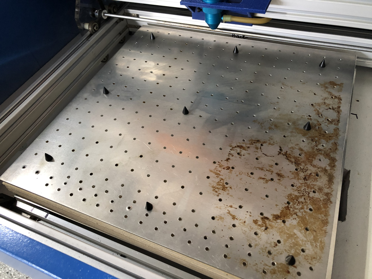
I had originally thought that I would place all 256 (16x16) spikes in the aluminum base, but when I actually used the pin table I realized I only needed spikes to support material that was left behind after the cut was finished. This led me to consider making the base out of steel by putting a thin steel veneer on top of the aluminum (thanks to @mcdanlj for the tip to NOT use galvanized steel) and placing magnets into the bases of the spikes so I can easy move and reconfigure their placement depending on where support was needed.
So…I’ve ordered this steel plate:
https://www.onlinemetals.com/en/buy/cold-roll-steel/0-0239-mild-steel-sheet-a366-1008-cold-roll/pid/12781
that I will fix to the surface of the aluminum plate and these magnets:
https://www.kjmagnetics.com/proddetail.asp?prod=D21
to glue into the base of the spikes.
I’m wondering if anyone here has a comment on this idea. Or, maybe, someone has tried this idea and is willing to share their experience (good and/or bad)???
This a continuation of how I modified my pin table using a thin sheet of cold-rolled steel onto the upper surface of the aluminum plate shown earlier. I attached the steel plate to the aluminum with double-sided tape. I used Krazy Glue to fix the magnets into the bases of the black spikes. For this step, I used 1/4" pegboard to hold the cones while I placed a drop of Krazy glue into the base of the cone before dropping the magnet in. I used a wood epoxy mixing stick to make sure the magnet was seated properly into the cone’s base. It looked like this:
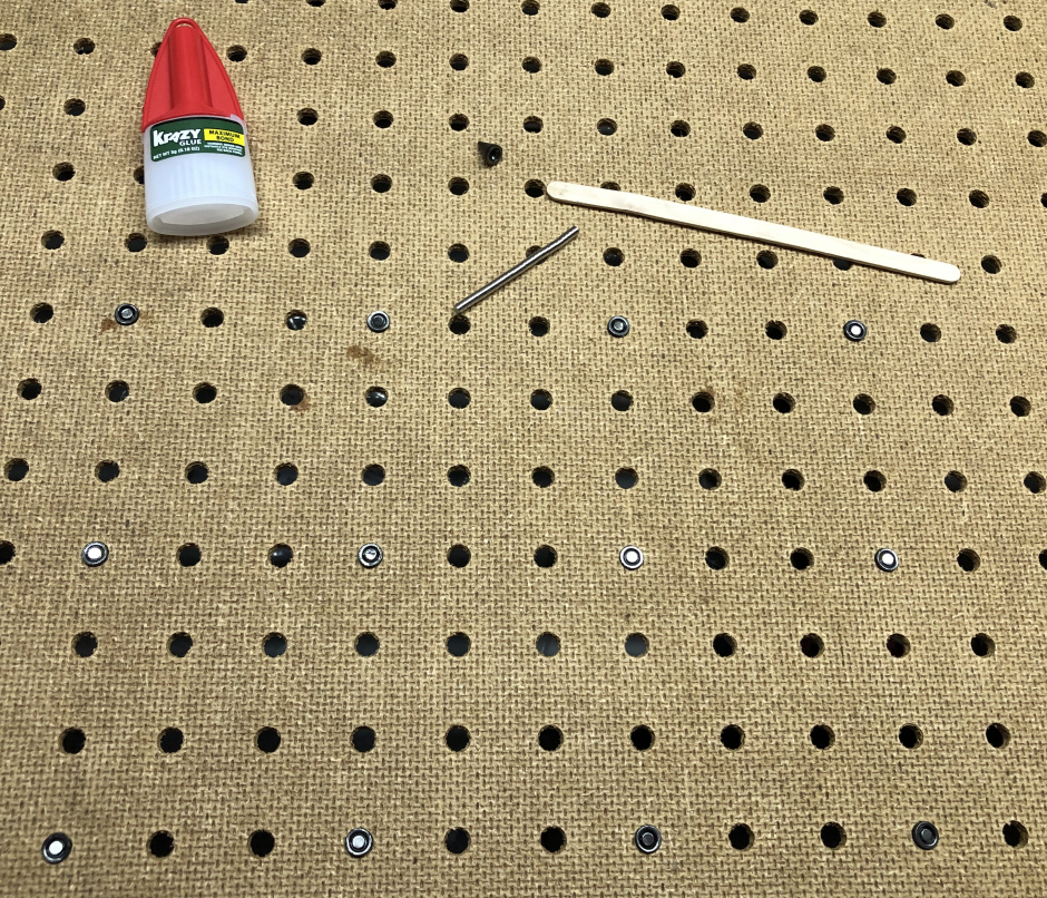
I had to keep them separated since the magnets attracted one another even spaced a couple inches apart.
I drilled holes through the steel-aluminum plates that matched holes I drilled in the top of the scissors jack and screwed them together with 4 sheet metal screws. I placed springs under the four corners of the pin table to provide some stability and support.
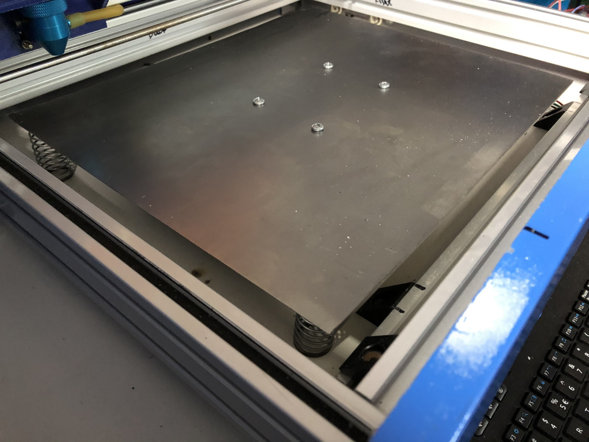
Here’s the pin table with the magnetic cones ready for placing:
Here are some randomly placed magnetic cones:
They’re easy to move around:
And, the Z-axis motor for the scissors jack handles the extra weight:
I believe this ready for some test cutting. For most materials I plan to use the cones. For rubber stamp material, I’ll place aluminum honeycomb on top of the pin table lacking any pins.
Bringing all this back to where I started…this new-and-improved pin table should make focusing and cutting easier to accomplish.
This topic was automatically closed 14 days after the last reply. New replies are no longer allowed.