From the console entering :$$

Sorry… attached an image… here it is typed out…
$0=10
$1=25
$2=0
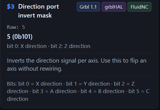
$3=5
$4=0
$5=0
$6=0
$10=1
$11=0.010
$12=0.002
$13=0
$20=0
$21=1
$22=1
$23=3
$24=25.000
$25=500.000
$26=250
$27=2.000
$30=1000
$31=0
$32=0
$33=0
$35=0
$36=0
$37=0
$38=10
$39=0
$100=800.000
$101=800.000
$102=800.000
$110=2000.000
$111=2000.000
$112=100.000
$120=20.000
$121=20.000
$122=20.000
$130-500.000
$131=500.000
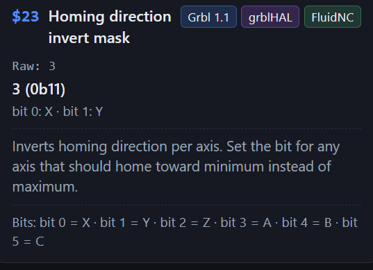
It now homes to the correct corner, its the framing that doesn’t work now. I can frame using lightburn but millmage will not frame, it tries to go out of bounds. I have tried to frame with both my laser and my cnc mill. With both programs. Lightburn frames just fine on the cnc mill and the laser, but millmage will not frame with either one… it is something with the program. It took me forever to figure out how to fix the homing. Both now home correctly in both programs.
If you do not get this right, you will Home and Jog, but it can still be operating in the wrong quadrant. Trust me, I learned from experience when I replaced my CNC controller board that was supposed to be a direct replacement.
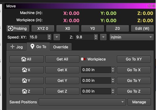
You have no work coordinate offsets, so this should be 0.0.0, or very close when you Home the CNC.
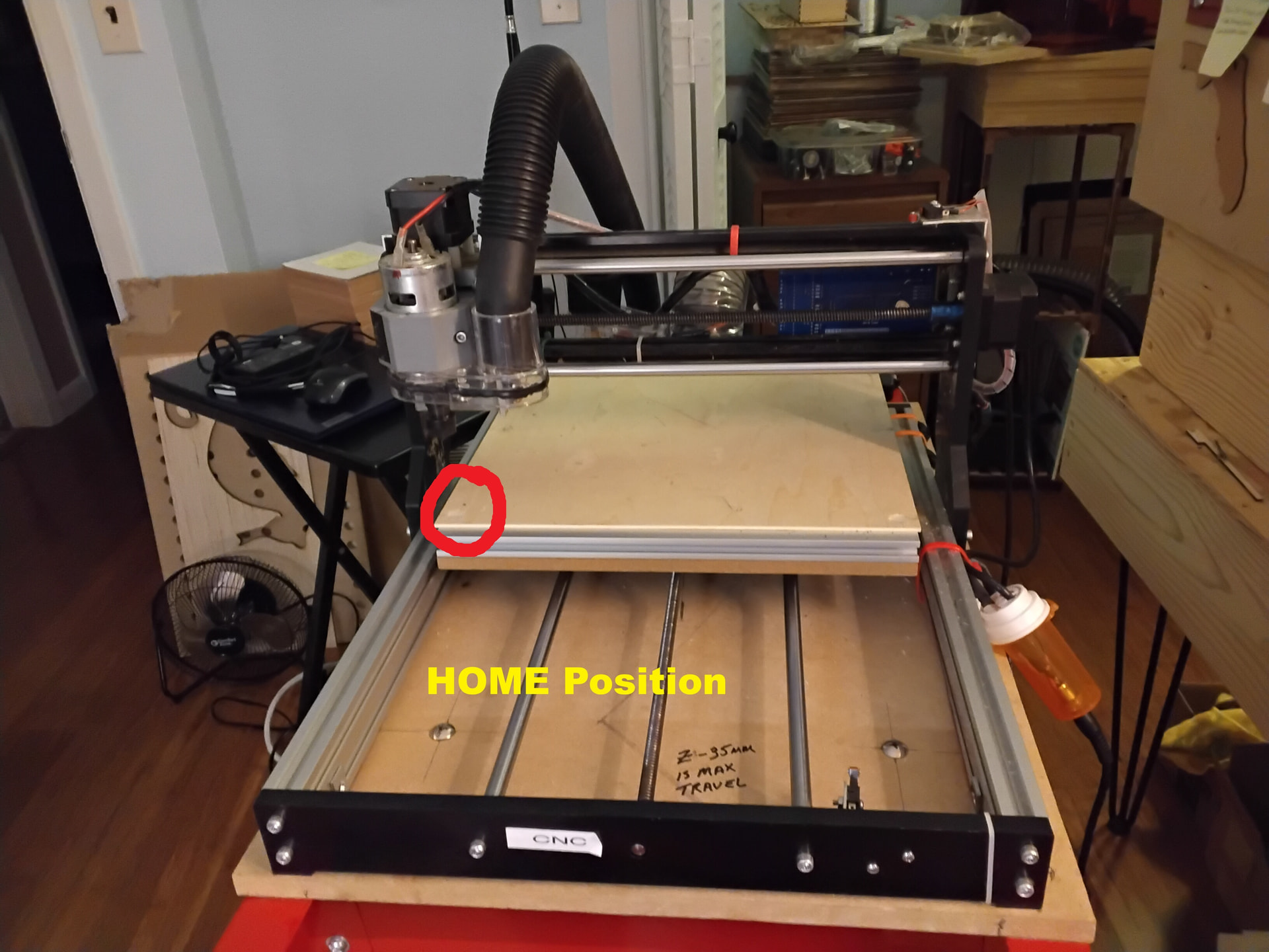
When it Homes, does the table retract and the laser move left?
Ok. I am very new to this… If you don’t mind, can you walk me through this… walk me through like you are talking to a grade schooler. Like I said. I am very new to this. I have only used easel to mess around with the cnc mill but i have never actually made anything.
i was green to the cnc world just over a year ago , everyone has a different concept , which is good and bad at times , what makes logic sense and is clear to some , will confuse the hell out of others
I found the best way to learn was read the docs, as your reading them, play with ur machine, at same time so you can visualise, when and if you change custom gcode or anything else, go to file /preferences /export , give each a unique name, its easier to reload an old config that works than pulling hair out after you made a small tweak and its now gone sideways
and you have to dive in deep not just test the waters which i tried at 1st , it doesn’t work , you need to see what’s in the middle before what’s on top makes sense
run a few full air cut jobs
I will treat you with respect, not a grade schooler. If I do not, tell me so. We ALL were newbies at the beginning. @wanderingtruckie, saying he started a year ago, is Now one of the top 5 people drilling into MillMage.
I see there are no work coordinate offsets, so that is a clue. Am I correct that Framing is your only issue (now  )?
)?
I will work up a test program and upload it later today (sorry I can’t do now).
I greatly appreciate both your alls comments and all the help!
Yes, I have learned so far. Got to delete the machine from the program and reinstall it several times (not sure how to set it back original settings yet). I have truly learned quite a bit so far… especially on how to get the homing to work.
Yes, that is correct, I have not been able to get it to trace the object yet. I think it has something to do with the coordinates, getting it to see them or something. I know I am missing a process or something that can be simple and I am just not seeing.
It’s only because of hitting the forums here have I been able to trouble shoot and fix the homing issue I had.. so trust me, I have been on here trying to learn. 
I really appreciate all the help you and everyone here have provided, thank you so much!!
wow seriously ? wouldn’t never of though that
 , only put it out there as human nature to try and skip the learning process, we just want things working now, :laughing I’m guilty of it myself at times
yes the forum is a wonderful thing , there are some very knowable people on here which have helped me so much
I am basing my opinion on your MillMage postings and the questions you ask. 
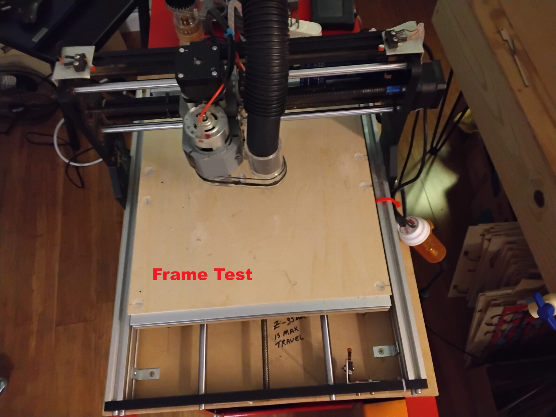
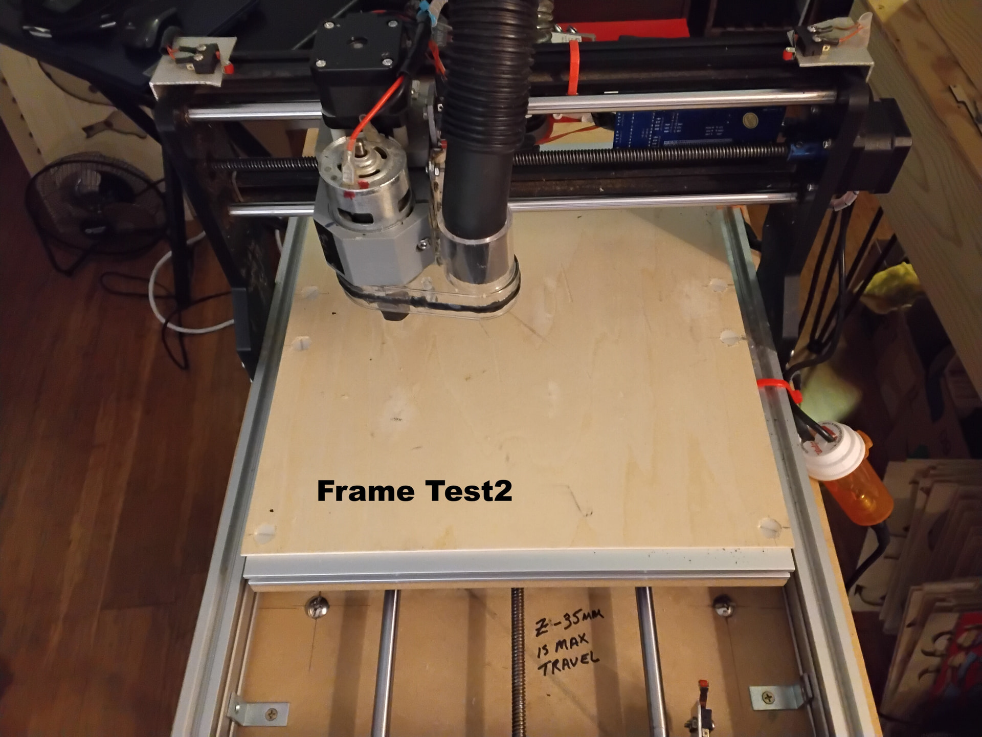
I have created 2 test files. The first has a material size of 380mm x 380mm and 2.8mm thick. This covers most if your CNC work area. The second is 100mm x 150mm x 2.8mm. This represents a typical piece of wood to engrave. I chose thin so the Preview would look nice.
I see “Ortur” in your Bio. I am guessing you use Lightburn. There is one major difference, Lightburn design space is the work area of your laser. MillMage design space is the size of the material you are cutting. However, MillMage is always Absolute Coordinates, meaning your front left corner of the block defaults to the front left corner of your machine. (For anyone else reading this, this is for her machine which homes front left and displays 0,0 in the Move window.)
First Image:
This is what your spindle position should look like when you Home the CNC..
Second Image:
The spindle should Frame near the middle of your table.
Third Image:
Although this is exactly the same design in the middle of the design grid, the spindle will now Frame near the front left corner on the CNC table.
Do the FRAME in each of the programs and let us know if you get different results than what I described. If so, then we have some homework to do. 
Framing Test.mage (52.0 KB)
Framing Test2.mage (65.9 KB)
We are here to help…
Yes, I have a Ortur Laser engraver and a FoxAlien cnc wood mill. It’s the wood mill that I have had issues with.
I will be trying these out tomorrow.
Thank you so much for these.
It looks like your $100, $101, $102 (X,Y,Z) step resolutions are too high at 800 steps/mm… probably should be just 80, not sure about your Z (400 maybe?). You can easily check by commanding a small fixed length jogging movement using the ‘Z Distance’ field in the Move Window, and then measuring the actual distance the Z axis travelled.
I’m guessing that is why you keep crashing, and why your acceleration/homing speeds in the GRBL settings are set low.
If it is a screw drive, 800 is okay. If it is a belt drive, then it should be 80.
@NicholasL and @MikeyH, Yes, you are both correct… my step motors were set at 800… I installed the Grbl generic driver… which has caused me to need to do a lot of trouble shooting… I changed the 100, 101 and 102 to be 80 instead of 800 and it is now framing the test frames Mikey sent.
Thank you both so much for all the help… I am sure there will be more issues to arise. But thank you all, @wanderingtruckie, @Colin, @MikeyH and @NicholasL for all the help!! It is more than greatly appreciated.
That’s good to hear! Although I think the Z-axis ($102) being on a screw will probably have a higher step figure than 80 - did you check the scale of that axis?
I plan on checking z axis speed today… thank you for the suggestion.