GRBL Fire Button

My laser has 3 Pins and in the grbl board it is connected to. 12V, GND and PWM.

Look at the photo I took. The laser is at off state even if the PWM lead is not connected to the board and turns on when the fire button is activated so that tells us that the 12V is being switched on and off and the laser is not just being controlled by the PWM pin.

I think what we can tell with the board and laser combo I’m using is that the 12V supply for the laser is being switched on and off but what makes me think is, even if the PWM lead is not connected right now. The laser is just in low power mode because of the fire button.


Playing around with M3 and M5 controls now got me thinking that the 12V is being controlled by the D11 PWM signal. I can have variable output without the PWM lead.

Hey guys,

I think I figured out how to do it with my laser. Turns out, my stupid laser works even without the TTL/PWM. No idea why tho. I connected it like this:

This is from the old 5V 1W laser diode I tried to use GRBL with (NEJE Laser). I think the mosfet acts as a current limiter depending on the PWM signal sent to it. Not sure if I’m correct. I understand that the proper way is that the laser will only fire when a PWM signal is sent to the PWM lead, right? Not sure why mine isn’t like that. It seems like the TTL/PWM is like a dummy lead. Like with my previous test from my original GRBL board, the laser turns on and off like it should even without connecting the PWM to the board.

Here’s how the laser is connected to the board. :slight_smile:

Your connect is wrong, The Z+ pin (Shield CNC) is PWM (TTL) Output, connect this to TTL on laser module, some GND pins (are many in cnc shield) must be connect with GND on Laser Module (connect with GND Power Supply)
Dont use D11 to energize laser module!!!
D11 (Z+ on cnc Shield) is only PWM TTL (0-5v) Output with few milli Ampers
You can connect laser module direct to 12V power supply and GND in common with some GND CNC Shield, and Laser TTL pin never unconnect, this conncet to D11 or Z+
“Sorry but English is not may language”

In my previous post, the D11 doesn’t energize the laser. The laser is energized by 12V power supply and D11 controls the mosfet which acts as a current limiting switch.

I did this and the laser fires up right away. Whether I short the PWM with GND, it doesn’t turn the laser off.

Amigo, usted no me entiende… no lo puedo ayudar, está la barrera del idioma lo siento

Power mosfets are NOT current limiting devices. They have a very low ‘on’ resistance, usually in the miliohms.

Pretty much when something lases, it is on or off, there is no useful state in between. Power control is an illusion.

I think you need to face the fact that your laser is broken.

My 500mw laser runs off the 12v being switched on and off by the control board on my CNC3018. It only has two wires. Notice there is NOTHING extra on this laser.

Yours requires three times the current to be switched as mine.

Yours has the connectors for PWM and the associated electronics.

These are cheap to manufacture and yours has ‘extra’ connections/components, if I’m to believe you, have no use. Didn’t cost the manufacturer anything for all these extra components…

You won’t believe us when we tell you it’s broken. :sob:

Good luck :slight_smile:

:smiley_cat:

If it works, then it’s not broken right, no idea why say it’s broken if it clearly works? The laser works just fine with the controller board and with the new circuit I made. The power can be regulated with the S values and goes to low power mode when “Fire Button” is activated.

Also, found out that my laser is not really “PWM”, it’s TTL but the TTL is connected on PWM on the board but doesn’t do anything. :smiley:

If yours is controlled by on and off, how do you focus it? You mean you cannot vary the power output of your laser and just go full power when it’s on?

It’s pretty clear to me it doesn’t work or you wouldn’t be here asking these questions. It might ‘light’ up, that doesn’t mean it is working. You really have no idea of how it’s really operating, except incorrectly.

If you have a stereo, in which you can’t change the volume, it still clearly works???

Yea, that’s because it’s broken.

With 12v power applied to it with the ttl input pulled low and it fires, your hardware is broken.

You advise it fires no matter the state of the PWM, confirming again that your hardware is broken.

Yes it is, the PWM circuit has failed.

The laser is a PWM laser or it wouldn’t have all that external hardware on it, along with connectors for ttl inputs.

:smiley_cat:

This doesn’t look broken to me. TTL may not work as intended but there are work around with it, not completely broken. lol.

Like yours, the laser can be controlled right? Yours doesn’t fire up 100% all the time right? How was that? PWM, right?

Who said that it only lights up? It works, it burns. Power can be controlled via S value.

What I’m asking here actually is how do I migrate from my GRBL controller board to the arduino+CNC shield and how to control the output power of the laser like the GRBL controller board. That’s the actual question. Like I said in my previous posts, everything works as intended using the old controller board and I just need to make it do the same with the arduino+cnc shield.

Then tell me how it should operate correctly. Can you explain to me how you control your laser power output? That’s actually the correct answer here. With the stereo analogy, who said I cannot change the volume? Like I said again and again, the old controller board does this. I can use fire button in low power mode and can cut perfectly in high power mode. What I needed is how to do this with the arduino+cnc shield.

LOL. the board clearly says it’s not PWM but TTL. The external hardware is for the fan and the built in power output control in the laser. You say it like you’re sure but it doesn’t apply in my case. Can you tell me where it says it PWM? Clearly it doesn’t have any “PWM” marking to me. TTL lead is a bust tho, if that’s what you mean by broken, then it’s broken in that aspect, in that aspect, means the manufacturer borked the design since that pin isn’t actually connected to anything. Checked the underside. LOL. My suspecion, they made it like that so people can use it as a direct replacement for true PWM lasers.Processing: VID_20211103_042146.mp4…

So here’s the real question. Can you control the power output of your laser or is it just 0 and 100%? If you can, mind telling me how do you do it, how it works, how it can be implemented to the arduino+cnc shield?

Look at my video, first on/off is from the fire button (low power) and then it cuts. Does that seem broken to you?

I’m not saying you can’t make it work. But so it burns, is that at 90% or 60% or?

What I meant by the stereo is that if you can’t control the volume, it’s still works fine as a stereo, just need to put pillows or something on it lower the volume. That’s what you’re doing…

If any part of the hardware is not working, how can you trust any of it to be ‘working’?

TTL is the PWM input, so it is a PWM controlled board. That means the controlling input is at TTL voltage levels.

The Chinese are not stupid, they don’t put anything on there that isn’t needed, please don’t pull the dumb card on me.

Mine is driven off the circuit that I showed previously. Maybe your old board does something similar. My laser is 500mw or 1/2 watt, yours is 15watts. The mosfet, although tough has a limit to how much heat it can dissipate without heat sinks.

If you have your heart set on this, use the schematic I posted with an N channel mosfet and the proper heat sink for your load. Most of the time mosfets burn open, so you could probably run one and see how it worked.

Screenshot from 2021-11-02 14-20-48

This is basically the same circuit. I used an LED since I don’t have a ‘component’ of a laser :slight_smile:
Driven from the pwm logic from your control board. The resistors limit current. I have stuff all over my house with no resistors there. I drive them right off the micro controller.

When the control line goes high, the mosfet is on and completes the ground to the led.

:smiley_cat:

percentage is handled by lightburn depending on the S value right? So whatever I set the value on it, that’s the percentage.

Those pillows work perfectly for me right now.

The main hardware for the laser is the laser itself right? Can I control the laser right now at any designated level I want? Yes? Is it working as I intend it to work? Yes?

Then it’s still not PWM. PWM has variable input/output. TTL will only act as on/off, nothing more. It won’t have variable input/output.

Then explain to me why the TTL pin from 3 pin doesn’t connect to anything in the board? Not even in the TTL 2 pin. The board I have has PWM, GND, 12V and that’s where the 3 pin is connected to. Disconnecting the PWM>TTL connection doesn’t do anything. So you mean, by that logic, it has a use? Note that this came in the bundled 3018. Board, motors, laser came as a package. All connectors were made for each other. Not sure why they opt for the 3 pin and not the 2 pin laser connection in the board since I think that’s basically the same since it works the same even without the PWM>TTL connection. What dumb card are you even talking about. LOL.

“Mine is driven off the circuit that I showed previously. Maybe your old board does something similar. My laser is 500mw or 1/2 watt, yours is 15watts. The mosfet, although tough has a limit to how much heat it can dissipate without heat sinks.”

And that’s is what I’m asking about. How to implement that into the ardiono+cnc shield. Your schematic shows 3 pins. How do you connect that to your 2 wire laser?

basically, the schematic you showed previously basically has the same function as the circuit I created and posted earlier. And it’s actually working right now like the GRBL controller.

“I think I figured out how to do it with my laser. Turns out, my stupid laser works even without the TTL/PWM. No idea why tho. I connected it like this:”

Fundamentally, your laser is basically the same as mine but mine has a built in fan and power output controller and a misleading TTL 3rd pin.

Can you tell me how laser power output is modulated by the schematic you showed previously since you said that mosfet is not current limiting. Then how is the power controlled at the same voltage?

Can you still say that my laser is “broken” like what you insisted? Earlier you insisted that it doesn’t fire up and I cannot control it’s output. Your pillow analogy doesn’t actually work on my case since it doesn’t have a built in “volume control”(PWM) like you thought initially and your analogy is intended to prove that my laser is broken because “I cannot control” it right? LOL it’s effed up that they used a 3 pin connector for nothing but my laser fundamentally works like your laser since like what I said earlier, TTL is not connected to anything and it works as intended even without it.

PWM is a digital modulation method, TTL is a voltage specification. When the TTL signal is high the laser is on, when low the laser is off. PWM is ‘high’ a percentage of the ‘power’ time. How long it’s on depends on what they refer to as the ‘base’ frequency of the PWM signal It’s really just the frequency as PWM itself is frequency independent.

A 1Kz base would complete a cycle every 1ms, so at 50% PWM it will be on for 0.5ms for every ms of operation. That is your illusion of power control, over 1 cycle it’s 50% power, over a million cycles, it’s still 50%. It is an average over time, not a laser ‘power level’. Your laser is lasing 100% when it lases.

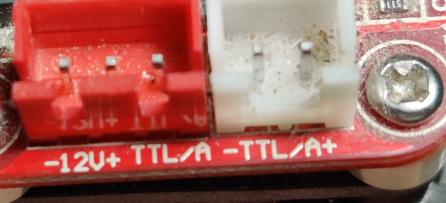
Very probably it’s a multilayered board and you can’t follow the trace visually.

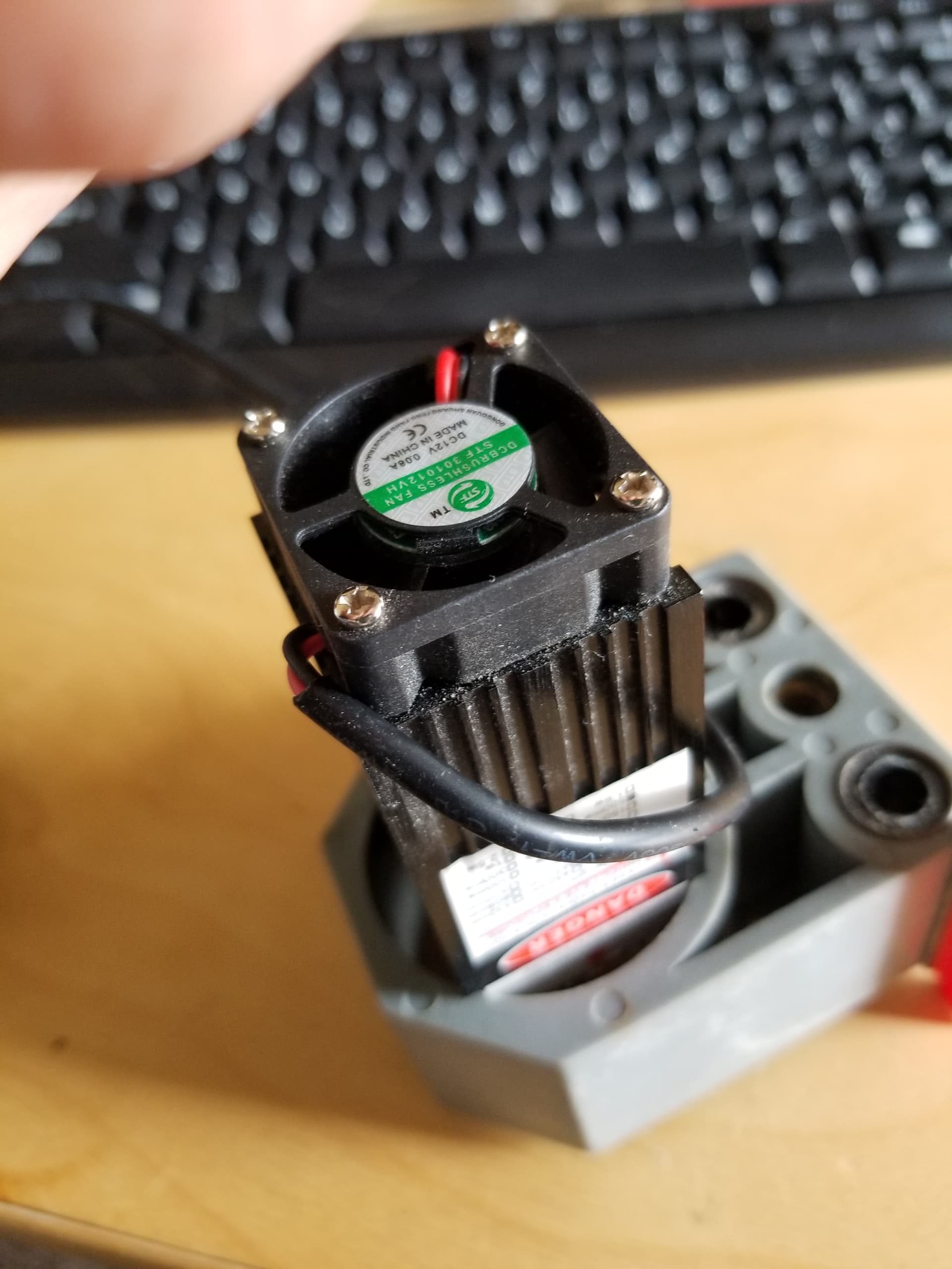
All of those components are not on there for window dressing, they cost money to buy and install. Not even Americans put stuff on there that increase costs for no reason. All that’s on most of the non PWM lasers are a fan, it runs when there is 12v to the laser and it’s on. If you think they put all that on there for nothing…

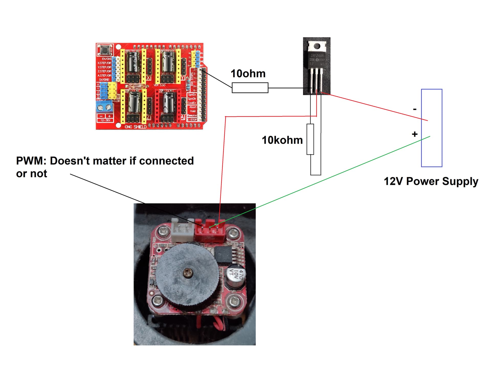
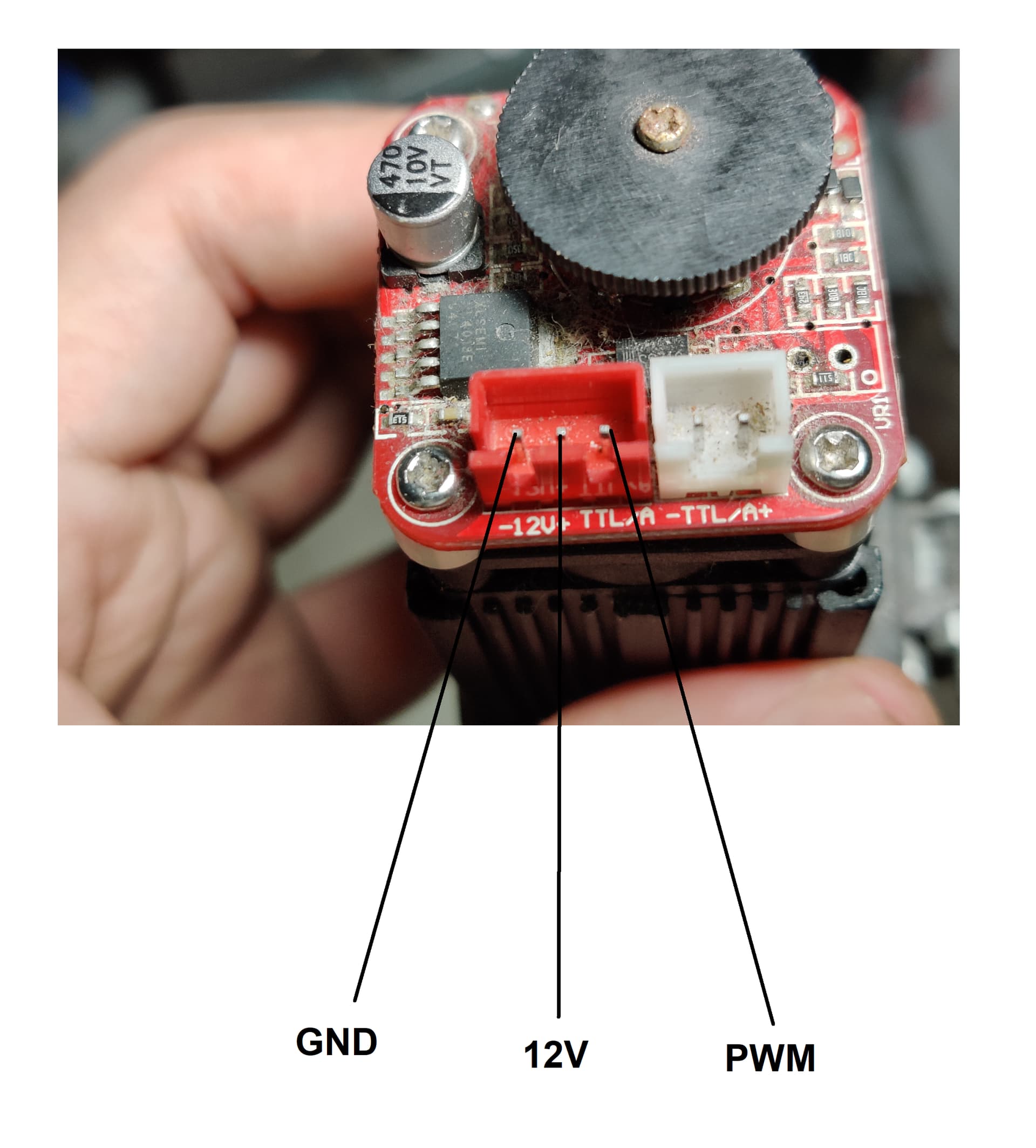
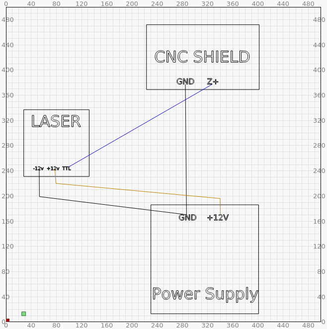
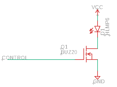
Just replace the LED with the laser. Positive side of laser to 12v and the negative to the drain of the mosfet. The source to ground. The third connection to the gate of the mosfet comes from the PWM at TTL levels from your board.

Screenshot from 2021-11-02 15-29-31

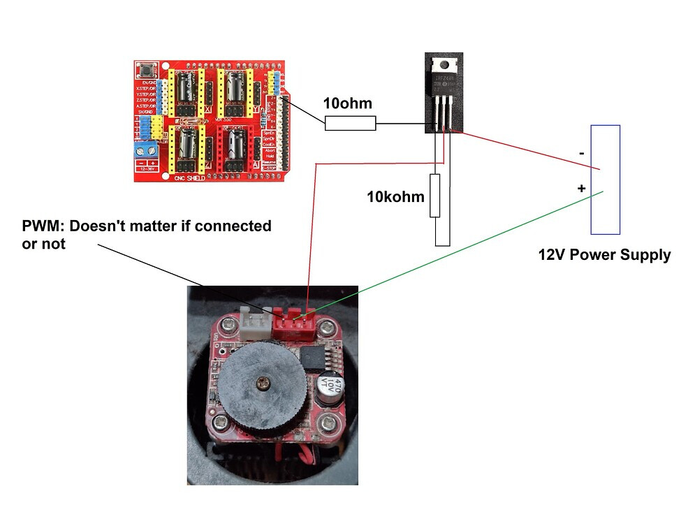
It could be like yours, but I can’t tell what the device is. Where did you get the resistor values?

If it works, run with it. You might find as with a lot of this stuff, if part of it fails, you don’t really know what you have.

I’d still suggest you fix it right, IMHO.

If I missed anything, let me know… :slight_smile:

Good luck. I’m sure you’ll have fun…

:smiley_cat:

This topic was automatically closed 30 days after the last reply. New replies are no longer allowed.