I have a K40 laser with an analog current gauge and a type 1 power supply.
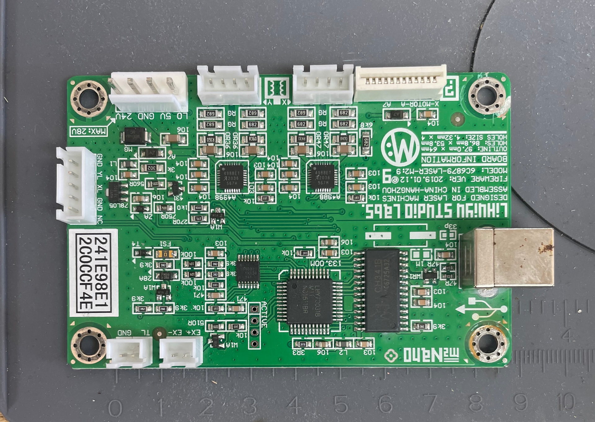
I bought the Monport GRBL board. There is no ribbon connection as the original board didn’t have it.
There is no connector block on the power supply for the laser control line.
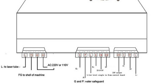
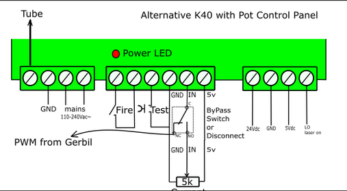
1/ ChatGPT said leave existing wires in place. Then connect the black wire of the control line to G of the G|P|L|G|IN|5v block and the red to L on the PSU
2/ GoogleAI said connect black to G and red to the IN on the block. Leaving existing wires in place.
The first option caused the laser to fire as soon as the machine was switched on
Can you please help me with regulating the laser power?
I can’t differentiate between the two AI models. I know I get laughable results quite often.
I would have to know what wire is what. The Chinese have, long ago, decided wire color doesn’t mean anything.
Do you have a pot on this? Sometimes this is used to set the maximum current limit and then the pwm works like it does on an led, turning it on and off.
Can you post a link to the board and your machine?
This machine has a type 1 power unit which doesn’t have a connection for the PWM laser control line.
I have gotten the laser to work by connecting the PWM wire to the IN socket of the PSU and the black wire to ground.
The issue with that configuration and retaining the pot is that it seems to act as a multiplier. So at the lowest setting on the dial and 0.5% in the software I get 2 mA at the laser.
I guess I can live with that but I was wondering if there was a better way.
I’m just learning LightBurn but it seems I can use Power Scale settings in the layers to give me a more granular control of power. So a 0.5 to 4% power range can be broken down.
Can you post pictures of the current and previous controller/psu/wiring setup? There are some different configurations of the K40 over the last decade+
What is the white wire on the “IN” port connected to? Presumably the Pot, in which case you will have issues; it’s either/or for this configuration. You can also connect the PWM out from the board to the “L” port, and keep the pot on the IN to get the “hybrid” kinda situation, where the pot keeps your power limit, and the PWM signal regulater the firing. I think that’s what you had with the first slop machine output.
It’s important to note that the K40 “L” signal is active low. Did you go through the relevant steps on this page GRBL Configuration - LightBurn Documentation for setting up the GRBL board? Double check that laser mode ($32) is enabled.
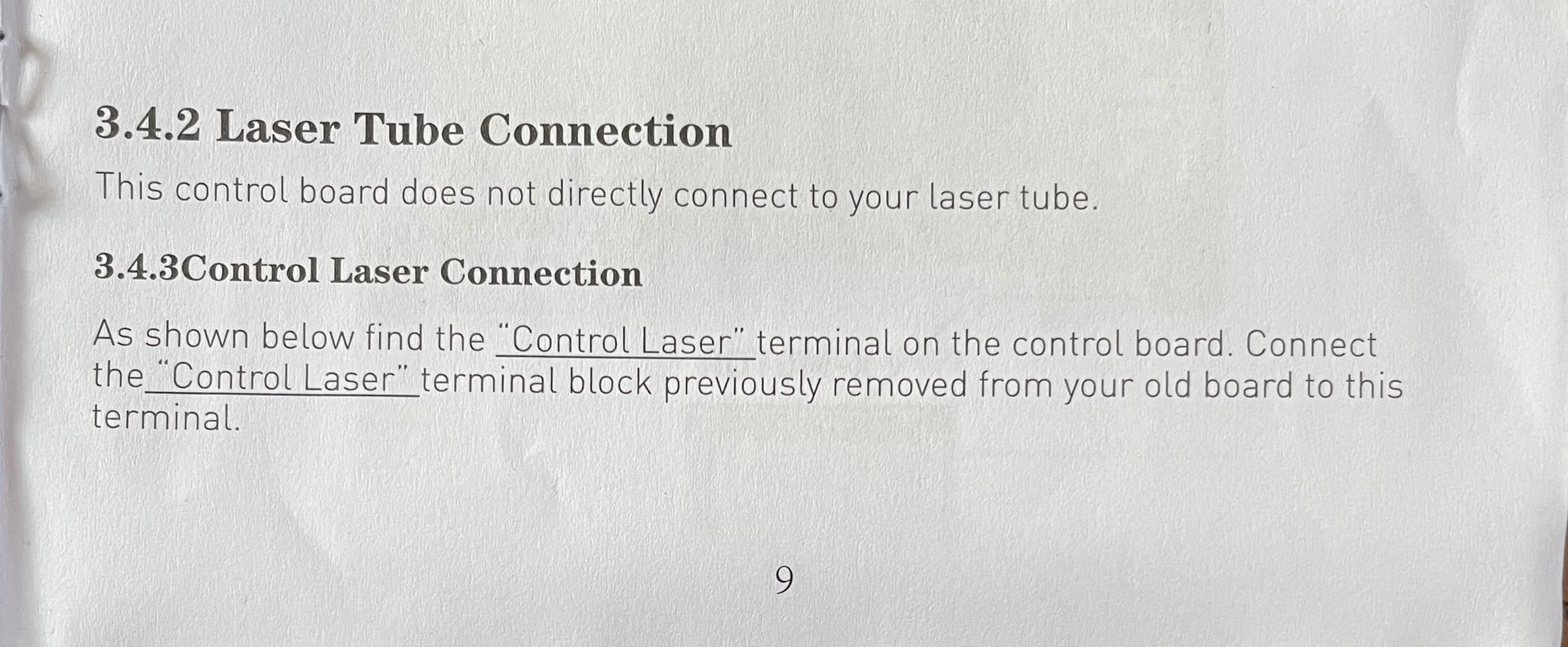
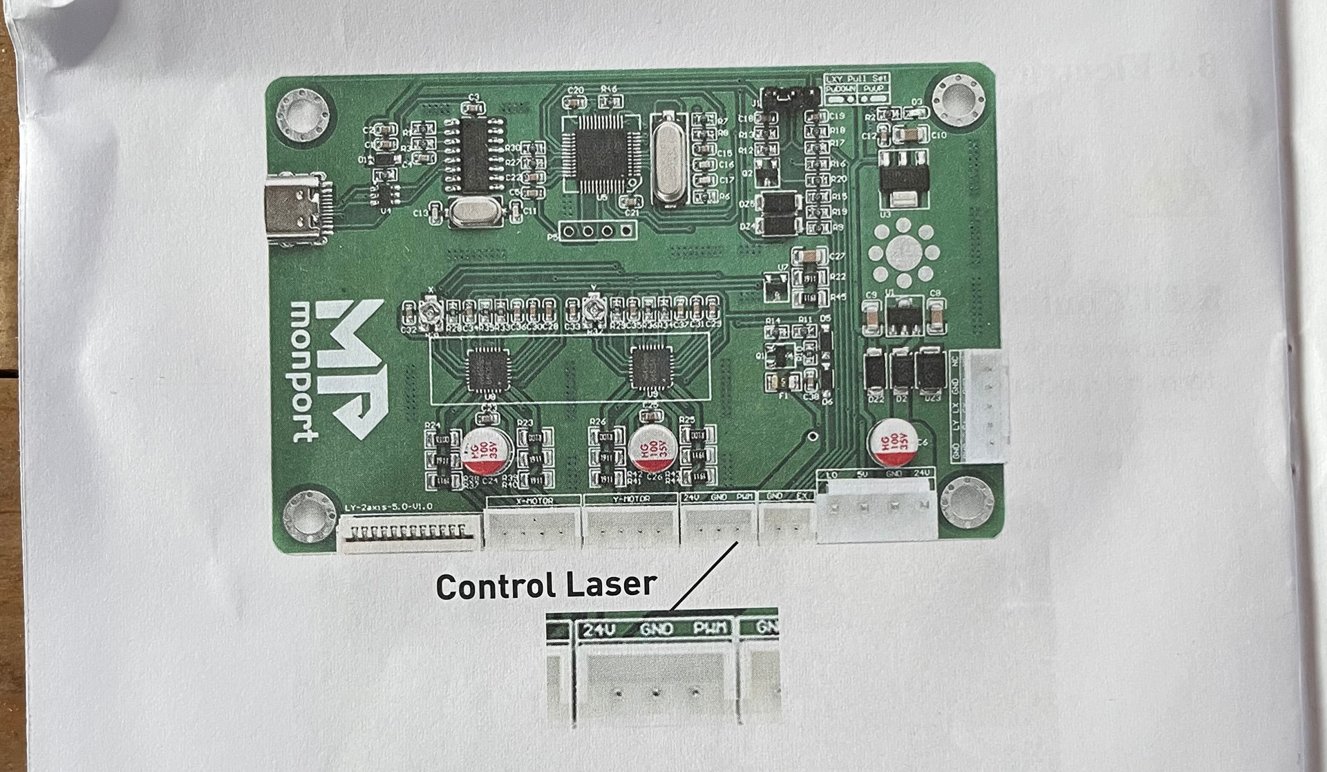
Do you have a link to the instructions for installing this board? This is from the Makers forum and is a different control board but you can use the connection to ensure yours is correctly wired and you understand the difference.
The pwm is required, one way or another, so there is a place. Hopefully the link will get you around this, The only question I have is if the pwm signal is inverted before it goes to L of the power supply.
Can you explain this set up please. Only the PWM wire is used and not the GND? My set up also doesn’t have the ribbon connector.
There was a guy on YouTube that used jump wires but that caused the laser to fire at start up.
My current situation is that I have the minimum setting on the power dial and that gives me a nice shallow engraving at 1% power on the layer (2mA) and 15mA at 50% on the layer.
I can’t set the dial higher because I can’t set the layer power percentage low enough to get the laser firing below 5 mA
I can live with this but Inwas wondering if there was a more elegant solution
After several tests it seems the best solution to have the PWM line connected to the IN socket of the psu and the other ground wire connected to GND
The power control is on minimum and is taken out of adjusting the power. The software is in control with a power range of 1% to 50% which effectively is 2mA to 15mA
This is down to the multiplier effect of this set up. I just have to make sure I don’t exceed 50%
After several tests it seems the best solution to have the PWM line connected to the IN socket of the psu and the other ground wire connected to GND
The power control is on a minimum setting and is not used at all. The software is in control with a power range of 1% to 50% which effectively is 2mA to 15mA
This is down to the multiplier effect of this set up. I just have to make sure I don’t exceed 50%
The only way to know what the signal is doing, is to have a common measuring point. This is usually ground. It’s assumed that all of these components have a common ground.
PWM is the only signal you have to work with.
Lack of information hurts all of us.. Do you have something, in text, on how to install the controller, so we can see what’s going on? We need to know or figure out which pin is the pwm.
These usually can’t lase at the 2mA you’ve specified, so something isn’t right.
There are two ways to connect these. One allows the software to control laser current, the other, sets the current at maximum, then it’s turn on and off with the pwm, like a diode laser.
You need to have a laser enable switch on your console, so it can’t laser unless the operator enables it. The pin names are the same and do the same thing.
I do not have a CO2 machine, but everything I have read says @jkwilborn was right to point this out. This is an electronics issue that needs to be investigated, or at least clarified.