I;m using a 80 watt CO2 laser and need to create a 1/16 inch deep and 1/16 inch wide with spacing of 1/8 inch apart.
I realize the depth is controlled by speed and power but I dont know how to create the 1/16 width lines or fill unless I go out of focus and need to have these engrave or fill lines to be 1/8 inch apart
Is it possible ?
My laser’s kerf is 0.115 mm and 1/16 of an inch is 0.1588 mm.
If you can figure out your kerf and set the spacing appropriately, you’ll get your width with just two passes.
I drew a single line, used outline (no delete original) to set the overall width to 0.115 mm. This represents the expected burn. Duplicating that and spacing the outside to 0.159 provided two centerlines that represent the two burns necessary to create a 1/16" burn in the wood. Once the block is defined, you can use the measured value to create similar outlines on your work.
The attached file represents a simple work-up because the math didn’t work for me on the first attempt and one word is worth one one-thousandth of a picture.
double kerf cut.lbrn2 (64.1 KB)
Set the power and speed to match the depth you require, although some experimentation is going to be required as the first pass will cut to depth and the second pass may put a bit more depth in the first pass.
Note to support techs: In the process of creating this file, I attempted to click elsewhere while in text mode. The cursor would jump to the existing text, even when output and show were turned off, preventing a different position for the text.
I’m not sure if I did something wrong or if it’s an undocumented feature.
It’s 1.59 mm, which definitely makes the problem more tractable.
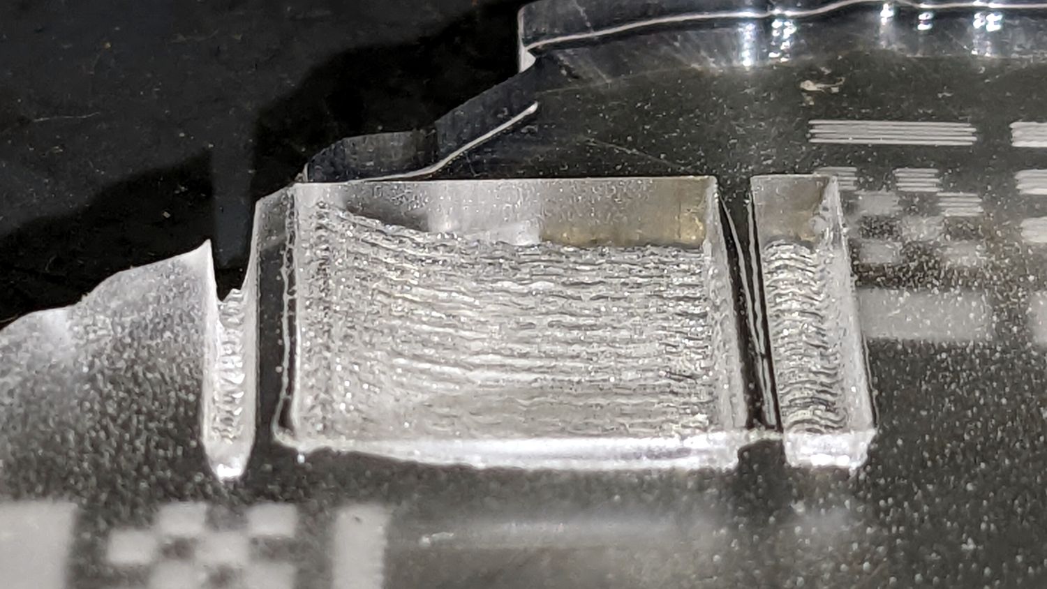
The trench on the left side is 1 mm wide and the one on the right is 2 mm, so they bracket 1/16 inch:
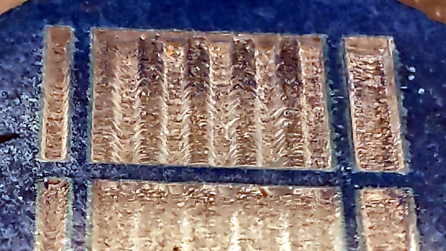
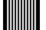
They come from the black bars on the sides of this test pattern:
It’s inverted while engraving to make black regions produce higher power: black = 100% and white = 0%. The grayscale sine waves in the middle produce corresponding power variations, with the depth depending on the power level. For rectangular trenches with a constant depth, you’d pick a power level to produce the proper depth, with no need for grayscale.
Seen in profile, the trenches (in a different test pattern) look reasonably square:
Those came from a grayscale ramp test pattern:

The depth depends on the power, but it’s obviously not linear!
Depending on the edge / depth tolerances and the material, engraving 1/16 inch wide bars on 1/8 inch centers should work just fine.
More details on my blog:
https://softsolder.com/2022/10/28/co₂-laser-tube-current-vs-analog-control/
Wow! I don’t know what happened to my alleged mind to generate that level of error! Thanks for the clarification/correction.
Most of the widgetry in my shop has hard metric dimensions, so my caliper spends most of its life set to millimeters and I depend on calculators for unit conversions.
Otherwise the answer is off by … too much. ![]()
double kerf corrected.lbrn2 (90.7 KB)
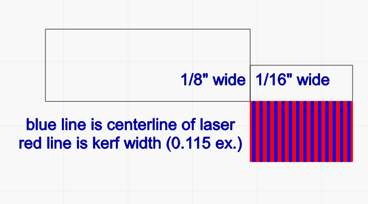
There’s a big difference when the layout is corrected! The attached file now represents the correct arrangement for a 0.115 mm kerf, which should be adjusted for the OP’s laser, of course.
Note that the file has some layers set to fill, for visibility ease only. For the original objective, they should be set to cut.
This topic was automatically closed 30 days after the last reply. New replies are no longer allowed.