Most of the help I have found concerns mostly Arduino and proprietary machines. I just added the new controller and limit switches and cannot get it to home. I get the following error when I start the machine:
Grbl 1.1f [’$’ for help]
[MSG:Check Limits]
[MSG:’$H’|’$X’ to unlock]
error:9
G-code locked out during alarm or jog state.
[MSG:Caution: Unlocked]
As of now the steppers are not moving…but I know they will. Everything else seems to work correctly. I just want it to home bottom left corner On the controller the socket has three pins but the switches I am using only have two. The switch wires are red and black.I am not sure how to plug it in. Currently I am using the black for ground and the red for signal. I am not new to this as I have several other cnc’s, a K40, and a couple of 3D printers…but I cannot figure out what to do to get the machine homing correctly. The controller had no English manual…I had to email the company to get the board model. I would appreciate any assistance. Thanks!
Would be nice to know what you know about the controller. Did you change the configuration on the controller to enable homing?
Most of these, along with my grbl uses NO switches and become active with when they pull the pin low.
If yours are NC then you will have to change the proper register ($5) to tell the controller that active is positive.
If it’s a three pin connector, it’s probably supply voltage, signal and ground. This allows you to have active components, such as hall effect sensors.
The order is up to the manufacturer but a meter will tell you if it isn’t marked.
The ones on my Woodpecker board were labeled X, Y & Z, but in reality they were Z, Y & X.
Yes…I enabled homing…in Grbl I assume you mean? I am using plain limit switches with no electronics onboard…my thinking was the open or closed state would be read on the controller when actuated. My thinking about limit switches may be wrong…I thought the circuit had to be NC. GRBL default is NO? The third pin in the socket is labeled 5v.
My current thinking is to buy an Arduino CNC shield as there are plenty of help available for them. I don’t know why I bought the board I did. If you, or anyone, could recommend one?
I appreciate your help.
For what it’s worth it seems that Annoy board is basically an integrated Arduino + CNC Shield. I don’t think going to that combo will really buy you anything in this regard.
In a 2-wire setup for limit switches you want the wires going to ground and signal. As @jkwilborn has indicated GRBL default assumes NO switches. You may need to invert the signal. NC switches typically call for adding a resistor to limit current to the switch. If your switch is mounted to a PCB it may already have it.
I wouldn’t recommend a hardware change. Learning how this stuff works is kind of ‘on job training’ and swapping out for no reason isn’t a good approach. If you swap out boards you will probably be getting the same message…
Since you run a two wire system with nc switches, ground isn’t used in this configuration.
It needs to pull the signal ‘up’… not down, so one side goes to b+
When I boot my machine, I get the following in the ‘console’ window
Waiting for connection...
Grbl 1.1f ['$' for help]
ok
[VER:1.1f.20170801:]
[OPT:VZHTL,15,128]
Target buffer size found
ok
Homing
ALARM:9
Homing fail. Could not find limit switch within search distance. Defined as 1.5 * max_travel on search and 5 * pulloff on locate phases.
ok
Grbl 1.1f ['$' for help]
[MSG:'$H'|'$X' to unlock]
[MSG:Caution: Unlocked]
ok
The error 9 comes from the fact that I don’t have the power to the motors on, so it fails to home within the allotted time.
You have the same error, so it isn’t configured/wired correctly.
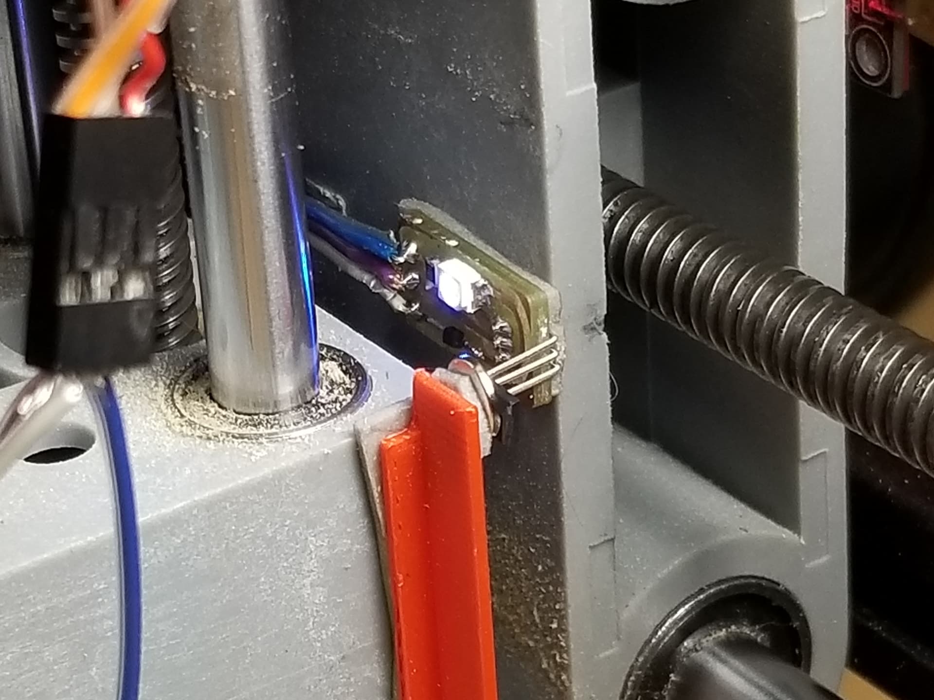
This is my Z limit switch. It’s in the center of travel and the magnets on each end trigger the hall effect sensor. The same animal is used on the end of each of the other axes. I have limit sensors at each end of all axes.
The switch has a lug for NO…I can easily make it that if it need be. There were several times when the stepper moved that it sounded like it was grinding and moving fast…I thought about too much voltage but I didn’t know what to do about it. I had them plugged into ground and signal.
The switches have a NO lug that I can change to if it simplifies things. I’m not sure what b+ means…nor pulling the signal up or down. I am using a 24v power supply as that’s what the company told me to use. I do have a 12v I could use. A few times the steppers sounded like they were grinding and moving really fast. Voltage? The controller has power inputs from 12 to 48 volts.
Your Neje module is 12V so unless your controller is regulating the voltage to 12V you’re going to have a bad time. Often controllers that allow multiple input voltages will simply pass the same level out.
Everything you describe are configuration issues not voltage nor the moons current phase…
My controller will operate just plugged into the USB, but no motors, spindle or laser. They usually have a separate supply and ‘board’ that allows you to connect the PWM signal to it for control at ttl voltage levels.
You will have to pay attention to voltage requirements for motors/laser modules and spindles.
Move the limits to NO and then you will have one wire to ground and the other to the input of the limit switch (signal).
I switched the switches (no pun intended) over to NO. “At startup” was the response. Could you look at the GRBL settings and tell me what may be the configuration problem? The X axis won’t travel as far as the limit switch before it stops with a limit error. The Y axis travels in the wrong direction when I use MOVE in Lightburn. I do appreciate all your help.
At startup
Waiting for connection…
Grbl 1.1f [’$’ for help]
[MSG:Check Limits]
[MSG:’$H’|’$X’ to unlock]
error:9
G-code locked out during alarm or jog state.
[MSG:Caution: Unlocked]
ok
[VER:1.1f.20170801:]
[OPT:VZHTL,15,128]
Target buffer size found
ok
You need to put the head in the middle of the workspace and power up the controller.
Note if the both axes are heading towards the limit switches.
The information you gave me tells me if some actions are reversed, but it’s different for different machines.
Again, the error 9 is it’s failing to home.
You need to pay attention to what you are doing. Doing something and getting it to work without know what you did is a loss to your education and to your ability to fix other issues that arise.
When we mentioned to invert the limits, you did. Then you changed the limits to NO and did not change the controller back to NO. $5 should be 0 for a pull down active state.
I expect a failure to home.
If you relax and think about what’s going on it will help a lot. We are here to help, take a deep breath…
I should have been more clear. I was looking for the link to your controller. I did find one Annoy board that takes 12-24V but looks like may output 12V for laser and stepper motor but not certain. So you may be okay with the output voltage. You may want to measure it before attempting to power on.
That’s the link from where I bought it at eBay…finding anything more…especially a manual, specs, whatever has been impossible for me. I misspoke about the voltage…it is 24 or 48 volts…apparently there is a voltage regulator onboard as the laser sockets are marked 12v or 5v…and so on.
I went ahead and ordered a CNC Sheld as there is abundant support online for the Arduino implementation…I already have an extra UNO…and I have worked with this before.The Annoy board is well constructed though…I am just not knowledgeable enough to figure the limit switch thing out.
I was told to put the laser in the middle of the work areas then turn on the controller and see which way the steppers moved. In short they don’t move at all when trying to home…but they will move in one direction when I use the move arrows in the move window. When I click home…the green progress bar runs to 100% and stays there but nothing moves. I tried moving the laser to several different positions…same results…however when I click “get position” in the Move window…anywhere I have moved the laser, and then turn on the controller, will report the position of all axes to 0. X:0 Y:0 and so on. I have Lightburn set to Absolute Coords. It appears home is where ever the laser is when I turn on the controller.
I have two 3D printers, a large and a small CNC machine, a plotter…a Co2 laser and the laser diode machine under current discussion. All but the plotter has limit switches…but none run GRBL…I have just bought Lightburn in the past week or soand I am not familiar at all with GRBL… I do pay attention…I am just in a learning curve.
It says to rehome…how does one rehome with limit switches? Thanks again for your help.
I have pretty much the same animal… It’s basically the same thing as you want to ‘re build’, the shield.
Not to mention, I don’t want to go over all this again. This is a configuration and wiring problem…
You’ve got enough knowledge of these machines you should be able to make this work. Without starting at ground zero…
The lightburn setup for grbl covers the 0, 0 home. Might want to go over it again.
If it doesn’t move when you power it up, do you get an error message on the console?
Like 9.?
If grbl fails to home for some reason (same with the Ruida), it thinks home is where it is. If it doesn’t have the home capability, it assumes that 0, 0 is where it’s powered up.
You have all of your ‘seek’ direction axes inverted,?
I’d suggest, remove all the limit switches and repeat the ‘start with head at center and see where it goes’. You will have to power it off, since there’s no limit switches for it to contact.
This will tell you if there is a wiring error in the limit switches.
Are you sure your CNC doesn’t run on grbl? My little cnc does as does my 3d printer.
I took a break. I have set Lightburn to Absolute Coords. All the steppers move in the right direction using the arrow keys in the move window…until I press the Home icon in the move window…then the progress bar moves to 100% and stays there until I right click the Devices button to reset…nothing moves. Zero (0) is wherever the axes are when I turn on the machine…and move into negative space when I use the arrows to move the axes towards home…front left. When I reverse those moves the axes will only travel to where they were when I turned the machine on and it zeroed at that location…if I try to go beyond that I get an Alarm 2… I do not understand why this is or have the skills to correct it. Any help would be much appreciated.
I suggest you start by confirming base configuration and that each component is working correctly.
When you first power on the controller does the machine attempt a homing cycle? The laser head should move toward home in both X and Y directions. After hitting limit switch on one axis it should stop in that direction and continue along the other axis. Once it reaches the 2nd limit switch it will stop in that direction but then immediately move away from both axes by a small amount then come back toward the switches at a slower speed, retrigger switches and then back off to come to final rest. Can you confirm this behavior?
Please provide the output from Console that’s provided from first power-on of laser
Can you take a photos of your limit switches showing the wiring and also wiring on controller side?
If you see this again, please take a screenshot of this or capture the output
5. Run these commands in Console and return results here:
When I power on the controller…nothing moves but there is a noise that sounds like the steppers engaged the timing belts. I disabled the auto home in the setup as the only thing that happened was the progress bar moving to 100% and staying there…nothing else. As far as I can tell…all the steppers move in the correct direction. I have two steppers on the Y axis…using the arrows in the move window. Click home in the same windows and the progress bar moves to 100% and stays there. I right click the devices tab to clear that. The laser works. I will get more information and send it…along with photos of the limit switches…this afternoon. In the meantime I will send the command reports you asked for.
$I
[VER:1.1h.20190825:]
[OPT:V,15,128]
Target buffer size found
ok