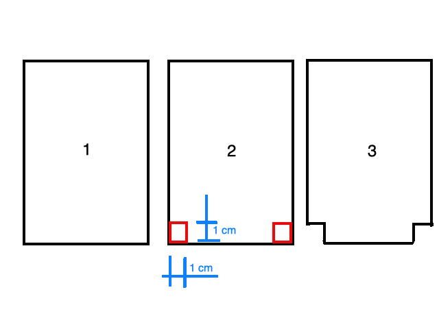
Hello all, I have the following problem for which i need some tips and tricks: from an existing piece of plywood that is 150x100 mm I should cut out two of the four angles so that at the end I have one side of the plywood that is 80mm , two sides that are 140mm and one remains 100mm. Please look at the attachment for a better explanation. The figure 1 is what I have, and the figure 3 is what I want to have. Thanks in advance.
I’m not sure if that’s what you want, but here’s my suggestion.
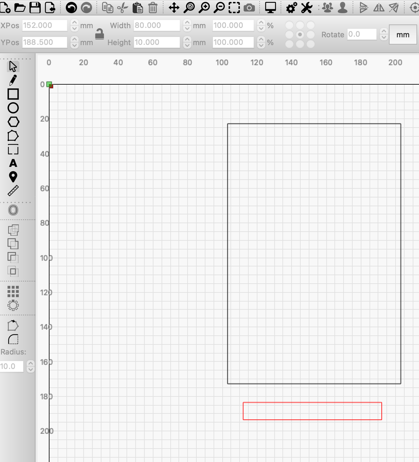
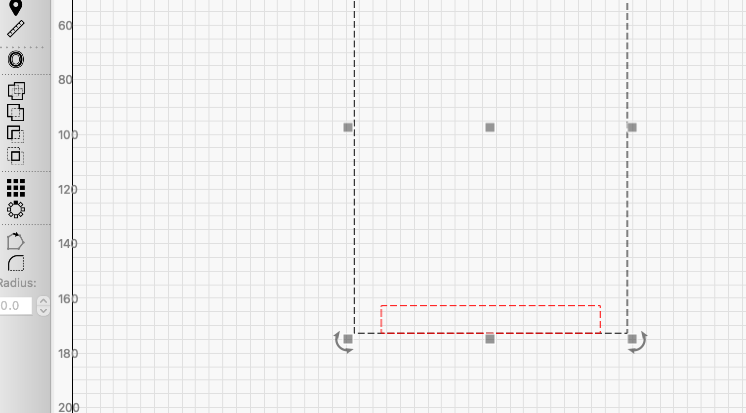
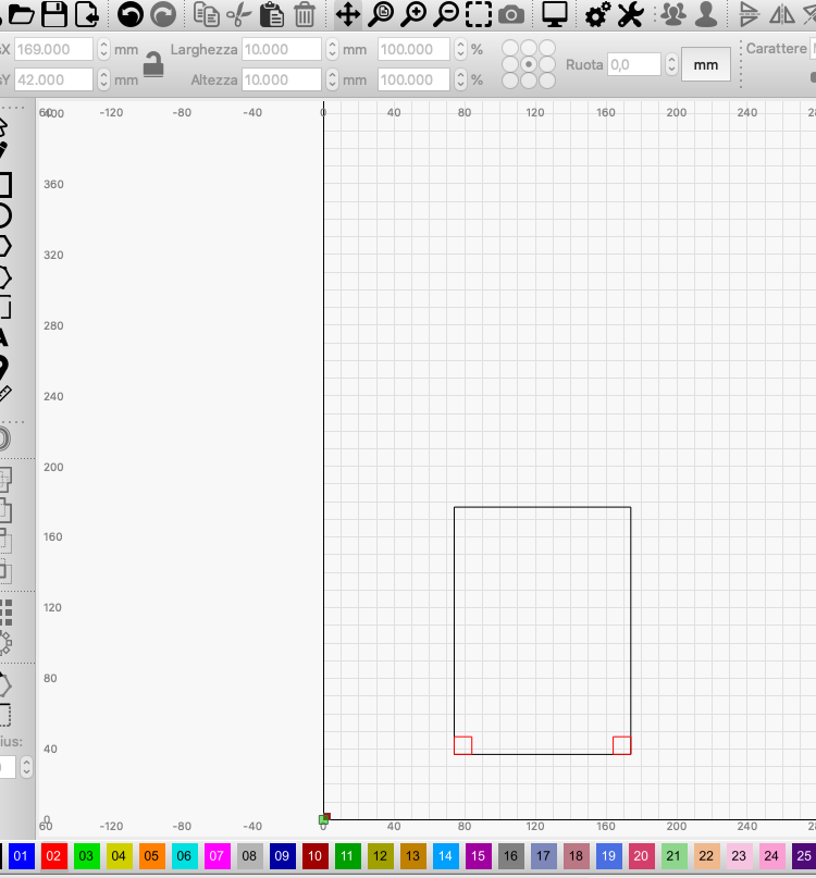
2 squares with the measurements you have mentioned, the red box is 10x80. You attach the red box to the bottom line in the center. Then it’s just that “Boolean Difference” - done.


Thank you Bernd for your suggestion, but unfortunately it’s not what I asked (sorry if I was not clear).
I try again in a different way. Here attached you will see the two cut (in red) that I want to make on the plywood (the piece of plywood is existing). My question is: how can I be sure to put the plywood under the laser in the correct way? It must be perfectly oriented with the sides of the plywood perfectly parallel to the axis of the laser machine. I have a Neje Master 2s Max. If anything is not clear please ask. Thanks Paolo
… sorry for the misunderstanding.
For this type of task, I always construct a jig. On my machine bed I have screwed a 90 degree angle oriented to X = 0 Y = 0, from that I construct my workpieces, for example if they have to be turned to work the other side as well.
For my A3 diode laser, I have also made a permanent, fixed table, both to avoid shaking of the machine and the workpieces but also to be able to set up a 90 degree angle.
A quick solution here and now would be to cut out a 150x100 square, only remove the square and use the outer frame as a template. But of course you must not move this frame.
1 Like
Your laser is best to use to create a “fence” for you to align your work at whatever angle you desire. I would try with a scrap of cardboard as a template to try it out. Once you have something that works for your plans, you can then produce said fence out of a longer lasting material if required. ![]()
thanks Bernd, it sounds interesting! Do you have some pics to let me have an inspiration to make mine?
Thanks Rick, also this is very interesting !
I have for my K40 3 pieces of them here, in different heights so they fit 3, 4 and 0.8mm materials and one one has many needle stitches just like a fakirbed. In the machine they fit directly to my machine frame and are screwed there too.
My A3 is currently being dismantled and I cannot find the bed right now. But imagine a flat plate that is a little bigger than the laser itself. Here I have screwed angles in which are also connected to the aluminum frame from my laser. Once in place, you will find another plate that you screw into the side of the X and Y. Now you cut it out with your laser, both axes in 0, it is the same principle as in the picture.
You can not get it more accurately.
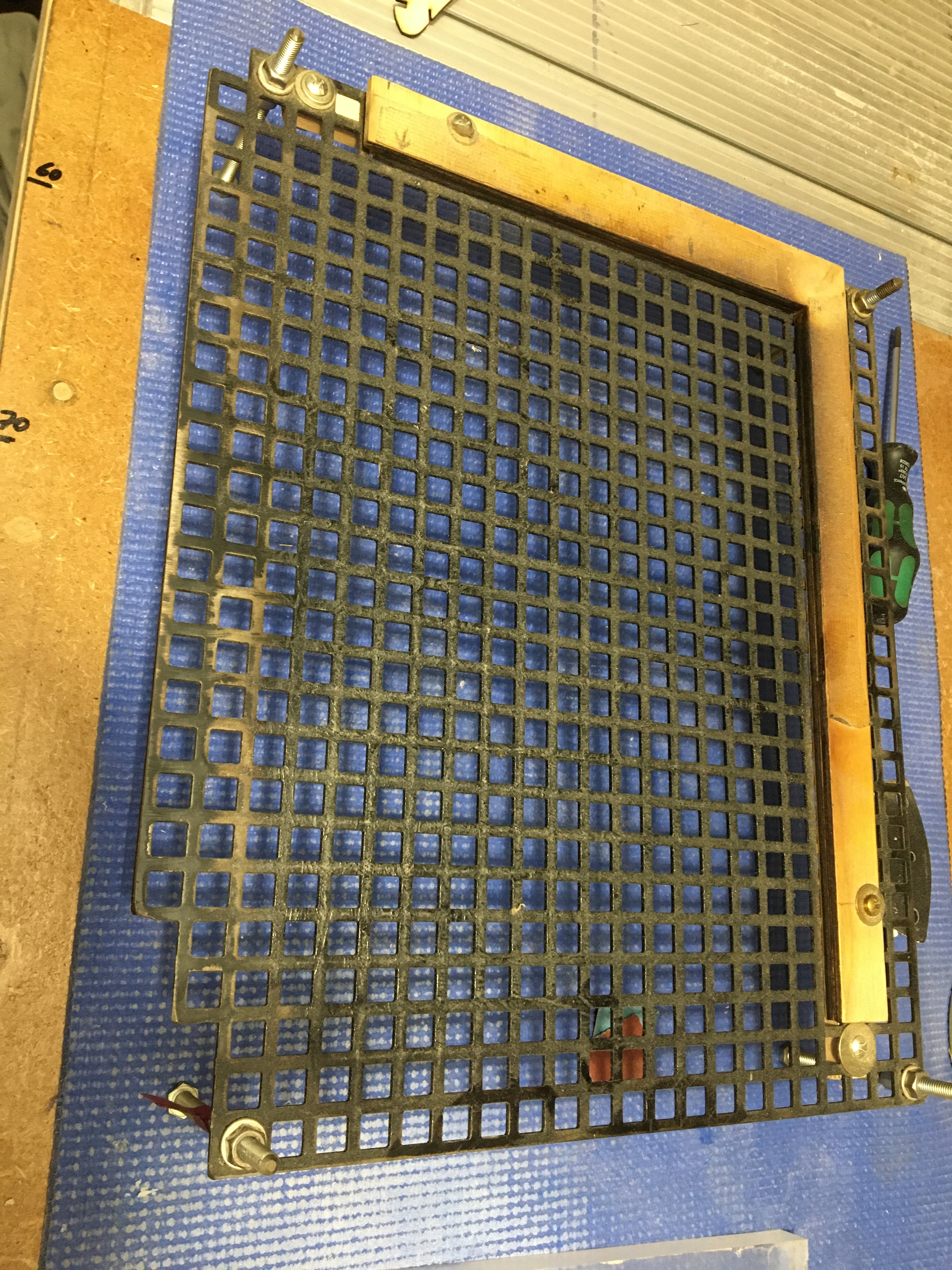
In the second picture is another solution which I was also very happy with. The perforated plate is fixed to the machine bed and fits perfectly with the holes in X and Z. With sticks or screws I can individually make my templates, I should have had it patented 

Draw a rectangle just slightly larger than your existing piece of material. Set that to a Line cut intended to completely cut through the jig material. Secure the cardboard to your bed and run that cut, remove cut piece and drop in your desired project material (your ply). You can now be assured your material is lined up with the X and Y axis of your laser.
I’ll add, draw the rectangle in the same file as your workpiece with the same origin. Then cut the outline with just its layer to output, then , when you’re ready to cut the workpiece, reverse the output layers. Guaranteed to be aligned.
Also, I use chipboard which is easy to cut, rigid enough for most applications, and inexpensive. (This may be what Rick is calling ‘cardboard’, but on this side of the pond that could mean many things.)
Thanks for the additional steps, I do this as well. Works a treat! ![]()
Correct sir, I am not talking about Google’s VR experience, or… whatever. ![]() I mean this stuff. What’s the name over yonder?
I mean this stuff. What’s the name over yonder?

Over on this side of the pond, that is called corrugated cardboard. Chip Board is similar (if not equivalent) to one of the thick layers in that stack up. It’s uniform density and probably about 1mm thick. Good stuff.
Here is a good example:
thank you all, guys !
It’s just what I was looking for : some examples to get inspiration !
Pizza and coffee for all of you if you come to Italy, thanks again !
1 Like
Oh, that sounds excellent. And we could use the take home box for the jig. Perfect! ![]()
1 Like


1 Like
I have a question in relation to orientation. I use LightBurn software and have a OMTech 100w laser. Since I am new to this, I went through all the setup and have started creating. My problem is when I orient my design on the UI grid, it does not match up on my laser. In fact it cuts it the opposite corner like a mirror image but the design comes out correct but upside down? Did I miss a setting?
Watch this video to see if it helps: Lightburn 101 - Starting Position, Origins, and Homing - YouTube
This topic was automatically closed 30 days after the last reply. New replies are no longer allowed.