I’ve just started using LightBurn and I have noticed two issues that would be excellent if they were fixed. Even more excellent if I’ve misunderstood something and the issues simply disappear.
First, when importing a DXF, LightBurn does not seem to preserve layer names from my DXF file. It is much more convenient for me to do my CAD in other software and import the final design as a DXF. It is also more convenient for me to assign layers in my CAD software, then in LightBurn assign cutting parameters for each layer. Even more convenient would be some kind of special labelling of layers that could be interpreted by LightBurn, so that a layer called, e.g. outline_2_120_50 would automatically create a cutting layer with two passes, 120mm/min, 50% power (or something like that).
The second issue is that LightBurn does not seem to handle the alignment of text objects. So, if I have a piece of text that is centred, or right-aligned, it always comes in as left aligned.
I am sure that a lot of people like doing CAD in LightBurn itself, but I prefer to use other software for CAD and just use LightBurn to handle the machine itself (i.e. performing the CAM functions only).
What cad are you using.?
We import from dwg via converting from autocrap.to dxf and it works there is just usually a couple artifacts and all letters will be doubled.
The best way is to imprint the letters .0001" deep or so into the part and export as dxf . and select The autocrap 2000 version of dxf. Using Inventor, thiis is the quickest most accurate way we have used so far. Once you imprint the text into the part, it quits moving around.
We have about 15 years worth of legacy corel draw files and when we convert them to dxf and import into lightburn all the color layers are there. And that is because the old laser only used the first eight colors of the lightburn palette.
I haven’t tried defining colors from autocrap yet, but I will tomorrow just for kicks.
Thanks for your reply. I am using QCAD. I don’t really see the point of assigning colours to my layers when they already have names, especially as the names are descriptive and tell me, for example, which parts need to be cut, and which need to be engraved (and which can be ignored).
I am running v0.9.24 (hey! There’s no Help|About… menu). I imported a job with some centre- and right-aligned text, but it was brought in left-aligned. Also, since I didn’t have the same font installed on the LightBurn computer it looked wrong anyway. I can get around that (mis-aligned text and missing font) by converting the text to vectors in QCAD, then they look right and have the correct alignment.
This is the way LightBurn, and many other laser software, works. You build the job based on layers. Layers are defined by color and not by name, as we do not know all the different ways one might name a thing. One might use the name “Cut” when they are wanting to “Mark” something. Which setting, in that case, should we select for that user when they import their work, settings to cut or settings to lightly mark the material?
In LightBurn, you place the art on a colored layer, which you can name, so you can visually “see” what you are setting. We also provide the ability to create template files and produce libraries of your art and material settings, so you can speed production once you have found the settings you like.
I realise that LightBurn defines layers by colour and not by name, however, I already designed my part in CAD and I already assigned different elements to different layers. When I import the DXF file all of my layer information is lost, and I am presented with all elements visible on the drawing area. Now I have to manually select individual elements and assign them to colours for the operation I want to perform. This is fine, except that I already did this in my CAD drawing, and the information is already present in the DXF file.
What I would like to see is when I import a DXF that the layers are preserved. The whole point of using a computer is to save time.
So, for example, I might have a DXF file with three layers: “outline”, “decal”, “guidelines”. I’ve done the design, and I’ve assigned the elements appropriately. I might want to send the job to a CNC machine, or I might want to laser it. When I open the DXF in LB I’d like to see the layers I already defined in the cuts list, maybe with a random colour assigned, and probably with no cutting information assigned (no cutting speed, number of passes, laser power %). That would be great. Now I know that all of the elements are grouped by layer in LB as they were in my DXF file. So, all I have to do (for this contrived example) is uncheck the Output box on the “guidelines” layer because I don’t want it to be lasered. Then set the appropriate cutting parameters for the “outline” layer- I want to cut through my material, and the “decal” layer- I want to engrave.
And regarding “Help|About…” I think you should have this menu item. I did “Help|Check for Updates”, which told me the version number (and that it was up to date). It’s not obvious otherwise.
This might be where the issue is, the color assignment is not random, LightBurn is trying to match the colors assigned in the original DXF file.
The way it is intended to work…from your favorite CAD design tool, you assign some of the objects of your layers to Black for say cutting, and some to Blue for vector scan fills, and Green for Offset Fills. This is just an example. You can have some other color set for another cut setting and so on. When you bring that file into LightBurn, the objects set to the color Black in the original should be assigned to the Black Layer, Blue to Blue…, helping to provide ease in design and production workflows. LightBurn provides the ability to save layer settings, create template files, use Variable Text support to auto-fill placeholders, and cut setting libraries known as Materials Libraries, all designed to help in this process as well. We believe when used in conjunction, the lasing process as a whole, from idea to final production, can be enhanced using these automations.
Are your shapes not landing on a matching colored layer when opened in LightBurn?
Is there a reason these can not also be colored say, black, red and blue? You could then have LightBurn open this file and have the cut settings already set based on the template for those colored shapes you labeled “outline”, “decal”, and “guidelines”.
Yes, exactly like this.
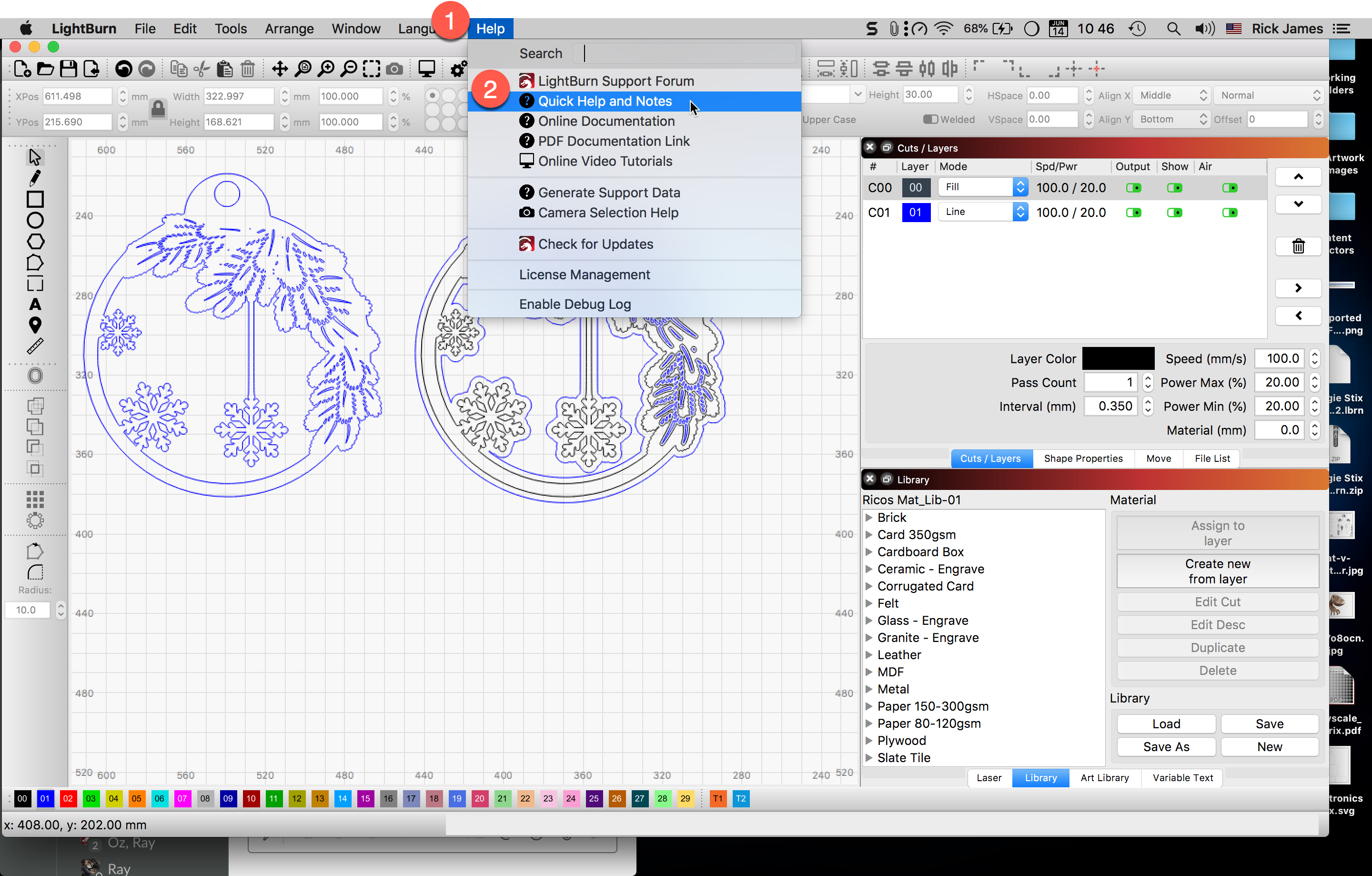
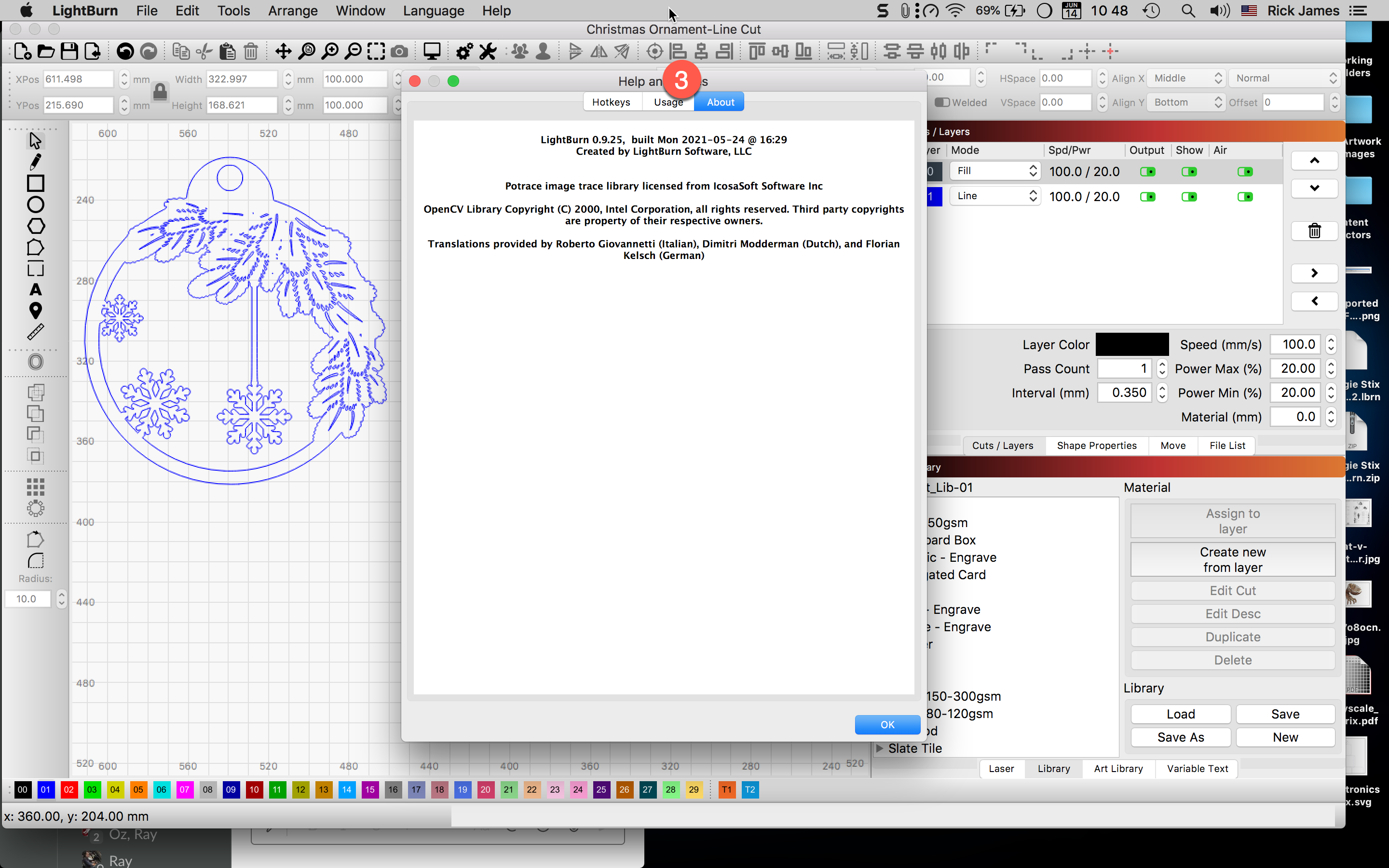
Did you see my 3-step process I shared in pictures? I show exactly where you can find the current version running. From the menu select, ‘Help’→’Quick Help and Notes’. Select the ‘About’ tab in the window that opens. The version is listed at the top of that tab.
Thanks for the reply. The issue is that LightBurn doesn’t handle layers defined in the DXF file, and I don’t want to assign colours in my CAD software. Or, in other words, I don’t want to change the colours in my CAD software to get around a shortcoming in LightBurn.
I completely understand how it is intended to work, however, I think it could be better. I suppose I should try SVG and see if the same issue exists with named layers vs colours.
Basically, you are telling me to assign colours to my layers, when I already have layer names. Perhaps I don’t want any colours in my CAD, or perhaps I might want elements on different named layers to be displayed with the same colour in my CAD.
To answer your question, all of the elements in my DXF file land on the C00 (Black) layer, which is the source of my irritation.
In my, admittedly contrived, three-layer example, the reason that the named layers can not also be coloured is because I don’t want different colours in my CAD (and I don’t need different colours in my CAD because they have different names). I should also clarify, when I suggested that LB could import the named layers and assign random colours I meant that the colours that LB might assign during the import were not important. They could be assigned based on the next available colour in a list at the time of import. Better still, forget the colours completely! Handle layers by name! I realise that this is a fundamental design decision which is probably baked in at the low levels of the software, but I think it was a very poor choice.
And yes, I saw the workaround for finding the version number. I still think that a Help|About… menu would be better, just like literally every other piece of software on the planet.
Sorry this discussion might be getting a little heated. I am quite happy with how LightBurn manages my laser cutter, however I am aghast at some of the design choices for the user interface. It is not my intention to be antagonistic, but in the faceless, toneless, medium of text it might seem that way.
Nor mine. Thank you. I understand your desired way of working. I am just explaining the way LightBurn currently works. We like suggestions and ideas / room for improvement, we are listening, so this has been informative and helpful.
Thank you for taking the time to provide a illustration of the process, however, it relies on assigning colours in the original CAD software, which is what I wanted to avoid, and which, IMHO is, or should be, unnecessary.
Upon further reading it seems that other laser software does the same thing (e.g. Trotec). It is equally as brain dead, and was obviously implemented by someone who thought it was a good idea at the time and didn’t understand layers. I suppose LightBurn could keep that functionality for people coming from other software, but I still think that importing layers as named layers into LB is a better solution. Then, as I suggested earlier, the layers could also have coded information in the name for the properties of the cut, further reducing the amount of effort required to actually run a job. This is a feature found in dxf2gcode, a Python program for converting DXF to G-code for CNC.
Unfortunately I suspect that organising layers by colour is deeply embedded in the software and unravelling it would be a huge effort, although a compromise could be, as I suggested, when importing a DXF, create a new layer for each defined layer, and assign the next available colour from a list. The workflow would be: draw stuff in CAD, assign elements to named layers, apply colours if you like, but they will be ignored by LB → import DXF to LB, layers appear in the cuts window, with a colour assigned by LB, each named layer has a different colour (for compatibility with the way LB works) → turn off the layers you don’t want, assign cutting parameters for layers that you do.
Even better would be the possibility to assign the same colour to different named layers, to attach the same cutting parameters. For example, I might have a layer called ‘outline’ and a layer called ‘holes’. I want both of them cut through with the laser, so I assign the same colour to each, let’s say ‘red’, and then configure ‘red’ to be high power with 3 passes (say) to cut through.
Either way, the fact that LightBurn does not support named layers in existing (or native) files is disappointing. I’d really like to discuss this as a genuine feature, even if it requires massive change.
The problem for me is that a great deal of artistic software defines a layer as a way of organizing related things, but there will be some filled, some outlined, etc., and LightBurn doesn’t have a mechanism for having multiple operations represented on a single “layer”.
We started using the color-map approach because that was already pretty much industry standard, and how existing users are accustomed to working. I’m not suggesting there’s no room for alternatives, but thousands of people are working with existing systems and files that expect thing to be this way, so we do it that way.
I do extract the layer information from a DXF, and could probably add a switch to make the system import layers instead of colors, but it’ll take some time to implement, and as of this moment very few people have requested this.
Use our suggestion site to post your suggestion and if it gets votes, it will be implemented. If it doesn’t, we’ll spend the effort on the things currently on the roadmap that people have voted for.
If you’re a software engineer and volunteering your time to do this, we can discuss via email.
I just thought about this a little more, and I seriously think a hybrid solution would work well. In a nutshell, layers are named, and operations are coloured.
So, for your laser you define cutting/engraving/whatever operations by colour, and layers by name. Thus, when importing a job (or creating a new job) elements are grouped by layer. Colours are assigned to the layer to specify what operation should be done. At the moment, in LightBurn, the colour specifies the operation and the layer. (And yes, you could have two colours with the same operation, but that is confusing).
Since I am in full control of my copy of LightBurn and I know the capabilities of my laser I can predefine common operations on common materials by colour in LB and assign them in advance in my CAD software. At the time of import I can choose to retain the colours (because I made the CAD file and I assigned colours to the layers in CAD knowing what operation I wanted), or ignore the colours (or I left them all as black), because I want to assign operations to each layer in LB later. In terms of underlying software it means that layer names are unique, but colours are not, i.e. several layers could have the same colour, because the elements on those layers should be cut in the same way.
I have already put the suggestion on your suggestions site. I might add this little refinement. I’ll let it percolate some more, but I think this encapsulates what I was thinking.
Sorry, this did not pop out the first time I read it. I think we’re probably talking about two sides of the same coin. In the case where someone has created a layer, and on that layer they have included two or more different types of operation (cut, engrave, fill) then I agree, it’s a problem. The original designer will have to add more layers and group elements of the same type of operation on their own layer. Since layer names are free-form the designer could describe related layers with related names.
For example, I have a current job in QCAD which I will use to make two pieces, with a common outline. I don’t want to define two files, one for each piece. Instead I have one file with several layers, and for one piece I will turn on some layers, and for the other I will turn on different layers, however there is only one outline layer, which is turned on for both. When both pieces are cut I will glue them together.
With a little more detail, here are the key layers:
construction (used for aligning elements)
outline
decal_lines
decal_text
decal_vector_text
bore
counterbore
There are three operations I want to perform: cut through 3mm MDF, engrave MDF surface with a line, and engrave MDF surface with a raster fill.
In my CAD all of the lines are the same colour. That’s fine. If the drawing is too cluttered I can turn layers on and off to see what I want to see. If they are different colours it probably wouldn’t help.
I want to be able to import that file into LB and make my two pieces.
For piece 1 I want the following:
construction - Off
outline - Cut
decal_lines - Off
decal_text - Off
decal_vector_text - Off
bore - Off
counterbore - Cut
So, piece 1 is a panel with an outline (outline) and some holes (counterbore) cut through.
For piece 2 I want the following:
construction - Off
outline - Cut
decal_lines - Engrave
decal_text - Off
decal_vector_text - Fill
bore - Cut
counterbore - Off
Piece 2 is a panel with the same outline (outline) and some holes (bore) cut through, with some lines (decal_lines) and text (decal_vector_text) etched on the surface.
I also want to be able to specify the cutting order, so that Outline is last.
decal_text is used only within the CAD program because LB does not have the same fonts installed, and doesn’t correctly handle different text alignments. So I have decal_vector_text which is text in the original font with the original alignment converted to vectors.
construction is also a helper layer in CAD which I use for aligning various elements, but it would never be cut.
From a cursory read, I think an answer to your issue is to write a small script that changes the files to what you wants.
I will acknowledge that I’m not too familiar with the inner workings of the DXF format, as Oz wrote that importer, but the base is an ASCII text file, and if you can simply add a color to each layer definition, that would solve the problem. You wouldn’t need to worry about all the complexities with NURBS and splines and all that head-bashing stuff.
file7 → file7_modified, then open the latter in LB and it all works without having to modify LB.
I imagine a larger solution could like like: https://www.bulkrenameutility.co.uk/ which I am a fan of, and you can process your trove of existing files as such.
Thank you for replying. I understand your suggestion, but I want to reduce the number of intermediate steps, which this does not do.
I could just colour my layers in CAD, but I don’t want to. My layers already have names, but because they are all the same colour (black) they end up all together on the same layer in LB.
I’ve seen several messages now where people are trying to use layers in other software and LightBurn literally throws away the layer information.
Generally the explanations for this are mealy-mouthed and feeble. Sometimes it even seems that the person is apologising for this dismal state of affairs, as if things are this bad because of reasons, and there’s literally nothing that can be done to change it.
It’s pathetic.
I tried re-doing a couple of my files so that elements requiring different operations were different colours. Not only did it look garish, but my layer names have meanings (which is why I use them). Sometimes I want to run the same job but with different layers turned on or off. Unfortunately, when the layer names are lost then the information about what the elements are is also lost. I need a cheat-sheet with colours and what layer they used to be, but this is pointless and really should not be necessary.