So I’m trying to familiarize myself with this laser I have. It’s an AtomStack M50 with custom 3D printed cnc platform I designed. I’m using a MakerBase DLC v2.1 GRBL control board.
I’ve been having good luck figuring everything out so far until now. I enabled the laser power button. I go to use it and the laser won’t turn on.
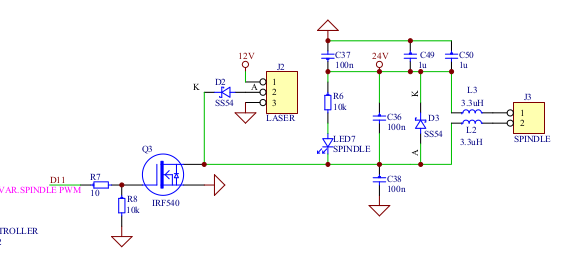
The M50 has a 3 pin deal going on, 12v+, ground, and TTL.
While probing the header pins on the board with the laser power button pressed, I noticed that my TTL signal works beautifully and not so much with the laser power header. I was only getting 1.3 or so volts. I probed those pins with the oscilloscope and noticed that it’s been pulsed as well. I’m seeing a pulsed 12v. What’s up with that?
The M50, like most lasers, comes with a control board of it’s own. I wanted to use it but I thought I would just power the laser directly from the board. The only reason why I can see using the laser’s control board is to provide an isolated 12v to the laser; that’s about it. Seems unnecessary.
What’s going on with the laser power header? Is LightBurn suppose to be pulsing it?
Which laser button is this specifically? Is this the Fire button in LightBurn? Or a hardware button somewhere else?
I’m not sure if I can parse this sentence consistently. I assume the laser power button is the same one referenced earlier. I think you’re saying the TTL signal issue doesn’t seem to be an issue with the laser power header. But please correct me if this is wrong.
Laser power modulation is typically handled as a PWM signal using TTL. Most typically 5V TTL but sometimes 12V or higher. Duty cycle of PWM determines power level. So 0% duty cycle would be 0% power and 100% duty cycle would be 100% power.
Seems that your board is using 12V for signaling which I’m surprised by. I believe DLC 2.1 should have 5V TTL for the Laser header. Which header are you testing?
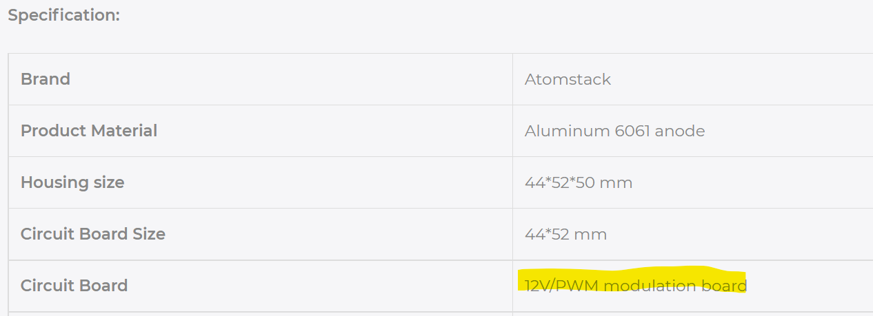
I’m not sure if the M50 is 12V tolerant for signaling. I see this on their site but it’s not clear if the 12V is referring to overall power or if it’s specific to the signaling. I suspect the former because I can’t imagine it not accepting 5V.
The board offers multiple ways of providing both power and signaling information. It also provides a test button that will generate a full-power PWM signal to make sure that the laser module is working irrespective of controller signals.
You can drive the laser from your controller given you have sufficient current in your controller power supply and that the board itself is designed for those loads. The M50 by itself will draw over 3A. This means you’ll likely need at least a 5A and more safely a 6A power supply at the controller. It’s typically safer using the board to provide a separate source of power to the laser module.
My apologies for the confusion; it was early in morning.
Firstly, I’m referring to the Fire button in LightBurn.
On the control board there are 3 pins I’m needing for my the laser to work properly, the two pins of the LASER header (12v and ground) and the 5v TTL signal pin of the TTL header.
When I push the Fire button in LB, the 12v source pin of the LASER header on the control board starts pulsing. The 5v TTL signal is pulsing too as it should.
I understand how PWM is used for varying intensity or speed.
I’m assuming the 12v source pin, of the LASER header, should be constant when the laser is in use.
So I just did a test to make sure the control board (Makerbase DLC v2.1) is working. I tried using another CAM program (EstlCam) and sure enough when I hit the Spindle button in that software, the LASER source pin and MOTOR pin are pulled up to a constant 12v. EstlCam is a program for milling though. I don’t know if the LASER and MOTOR pins work the same for both a laser and spindle.
So, my laser isn’t turning on and my 12v LASER source pin on the board is being pulsed. I know that LightBurn is doing responsible. Is the 12v source pin suppose to be pulsed?
Ok. I figured it out. It was the wire I made to couple the laser to the board. I had the wires in the wrong order. As I said early, It was early in the morning and I was tired.
Everything is working fine now. The beam turns on at the 1% I specified in LB and the laser’s fan is working fine too.
I’d still like an explanation of the pulsing 12v laser source pin on the control board. It has a duty cycle like that of the TTL signal. The fan wouldn’t be working with a duty cycle of 1%, but it’s working full speed right now.
Oh… do you know what pins I’m to use to power the air assist pump?
Got you. I’m following you more closely now. I believe the laser header is normally used to power a non-PWM laser. So basically on and off. II don’t think it’s intended to supply power for a PWM laser. I think you could pull 12V power from J20, assuming you’re running a 12V power supply. I think J20 provides 12/24V depending on power supply voltage.
Not sure about best sport for air-assist. I suspect you’re only expected to wire one of J18, J19, or J26. But could be wrong.
This is my Woodpecker controller from my CNC3018 grbl. It’s probably something similar on yours.
Mine came with a 500 mw laser that had only two wires, so all the control board did was to complete the ground to the laser to turn it on. Notice the connection to the spindle works a little differently.
Even with your cam program, you should have the ability to change the spindle speed. As you can see it’s directly connected to the pwm output…
I think your board is configurable, I’d ensure it’s set up correctly
With the laser, being three wire, it depends on a supply voltage, ground and the pwm signal. So I’d suspect there is some other options to drive the laser.
Many of these laser modules, have external supplies and the idea is the same but you only need the pwm source…