We finally have got lightburn working more or less perfectly on our K40-s Thanks for those who helped.
One final query, in the end we used a mks makerboard with grbl -LPC and we want to be able to home it properly.
Does anyone know the best end stop switches to use and the type push to make or push to break or a 3 wire with Ground, positive and Signal as the board has this on it.
On one machine we have maker block end stops taken out of a old frame and they seem to work by using the signal and ground contact on the board and when you push the switch it makes contact and homes fine but
I cant get hold of these end stops so I was wondering what to use on my machine and whether to use all 3 pins in the control board.
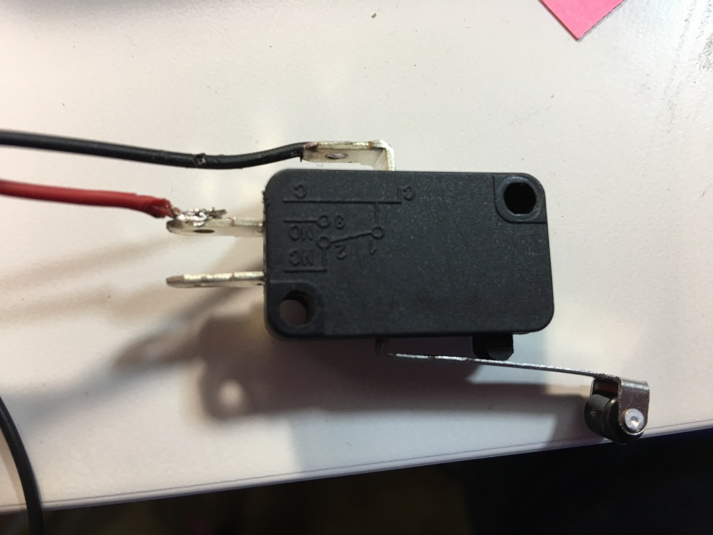
Do you need special end stops with these sort of boards, I have wired up a couple of normal roller end stops and use just 2 pins of the 3 pins on the switch push to break and it sort of works but not properly as after a two or 3 times testing it go-s from the move window to the console window and below in the laser window where it says ready when you push the switch which stops the carriage it says disconnected release and it says ready and carriage is ready to go again so it would home buy doing it with these, I just dont think they are the right switches because of the move to console thats going on.
You don’t really need anything special for endstops. The optical endstops that came with the machine are what I still use.
Sounds like you might have your endstop wired up some other way than typical, can you post pictures by chance?
Ideally you’d turn pull up resistors on (default state is then 5V on the pin) and connect the switch from GND to SIG with the COM and NO pin from the endstop. When the endstop gets pressed you “short” that 5V to ground through the pull up resistor to limit current.
The three plug endstops will have the current limiting resistor on them. So they take “raw” + on one pin, raw “-” on the other, and they take care of defaulting the pin to high or low and then only sending a tiny bit of current when the switch opens/closes.
Ok thanks very much for that, yes here are some photos, I meant to add to the questions and forgot I know I can set a origin very close to the normal 0,0 on the k40 and then use set to origin temporary but is it possible to set a permanent soft homing then I wont bother with switches at all ?
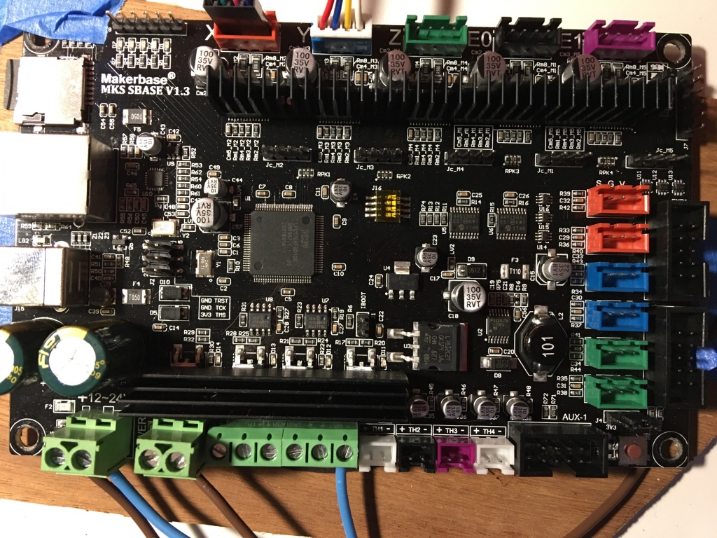
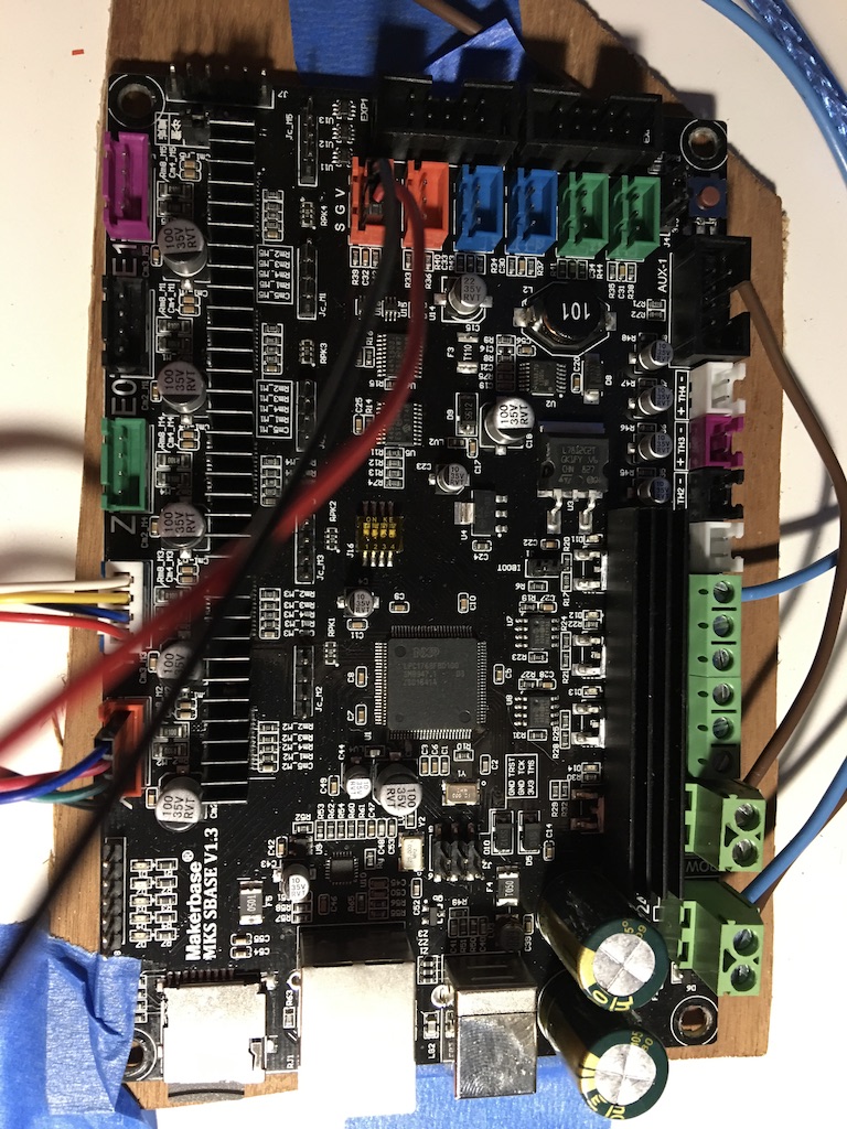
Here are the photos its a 32-bit Control Board for King Print MKS SBASE V1.3 Smoothieware 3D Printer MC board running a version of GRBL.
The pictures are of the board, the board with the pins in of one of the switches and out just so you can see the board.
To be honest it sort of works, just every now and then it will go to console because i am testing the switch by jogging the x axis at 100mm and pressing the switch it stops the axis so I would assume it would home but because i do it 3 or 4 times to test it it then goes to console, on my friends machine it doesn’t do that and doesn’t say disconnected… By doing it once by going to home and not several times it wouldnt jump to console. But Im concerned about damaging the card.
I have to admit it runs the laser very well.but my electronic skills are not the same as yours by the sound of it. Thanks for any help though. best regards
FWIW, I like to set my end stops on things to normally closed/NC( ie when triggered they are open/NC ).
This is because if/when there becomes a broken endstop wire problem it will trigger the endstop.
If set to NO so triggering is on closed, during operation you’ll never know if/when a wire becomes broken or disconnected and the next homing operation will not go well.
Are the original end-stops gone or did you buy/make the ribbon breakout? Or did you just not wire them back up when you swapped the stepper cable from the ribbon to a wire? I have my originals in still interfaced with the ribbon cable. I send them 5V and GND and then take their S pin right into the endstop’s S pin.
Your wiring on the end-stop looks correct, though to Doug’s point I’d switch to NC. My K40 is running Marlin 2.X instead of GRBL. I have the 2209 version of this board on the way here for it as well to replace the current MEGA2560 board in it.
I havent yet taken the end stops out, I was wondering about doing it tomorrow, ,Does the main ribbon do X and Y end stops?
I am not electronically minded would a easy idea be to just buy a 3 cable end stop off ebay and replace all the ribbon cables and so on, I see a few are on there, I just dont know if the board would take the end stop. I found these on ebay which would fit but I dont know if Its as simple as that. It doesnt worry me spending a few pounds to sort this rather than try to make something if something is already made and will do the job. I have already had to replace. one stepper motor as it was rotten from new, then recalculate its size in T2 as the rotor on the end is different to the original one, replace the board and so on so another tenner wont matter if there is something off the shelf I could buy, I know you guys and gals on here like to tinker a lot but I prefer just to get on and make things i can sell and leave the tinkering to those who are better than me. Would that work and could you point me in a direction of what would work if my link is no good, I can only buy from europe though. Many thanks…
Your easiest option would be to search for and buy a “K40 breakout board” – It has the ribbon cable connector on it and then labeled pins for +5/GND, X, Y, and motor. I like the idea of optical endstops on the K40 because it means nothing actually contacts. Looks like “Awesometech” sells one for 15 USD. I made my own breakout on perf board first and then re-did it with a CNC PCB mill. I like the ribbon cable for what they’re using it for. Not having to worry with all those separate wires binding, chaffing, etc.