Kerf offset will not be applied to that green tabbed shape because it’s not a closed shape. Open shapes have no inside or outside to offset towards.
Only closed shapes will get offset.
ETA: If you are having trouble getting kerf offset to work, one of the first things is to verify that your shape is truly closed and not just a collection of lines that look like a continuous shape but aren’t really.
ETA ?. I duplicated the above with straight lines and it didn’t work. About to post there was a problem with LB or my laser. This is probably my problem. I’m going to do some more testing right now.
Once you’ve done your thing with the straight lines, select the shape and go to Edit > Auto-join Selected Shapes (Alt+J) and see if that closes it for you.
If do Edit > Select Open Shapes, it will show you which ones are open. If it ain’t closed, it ain’t gonna offset…
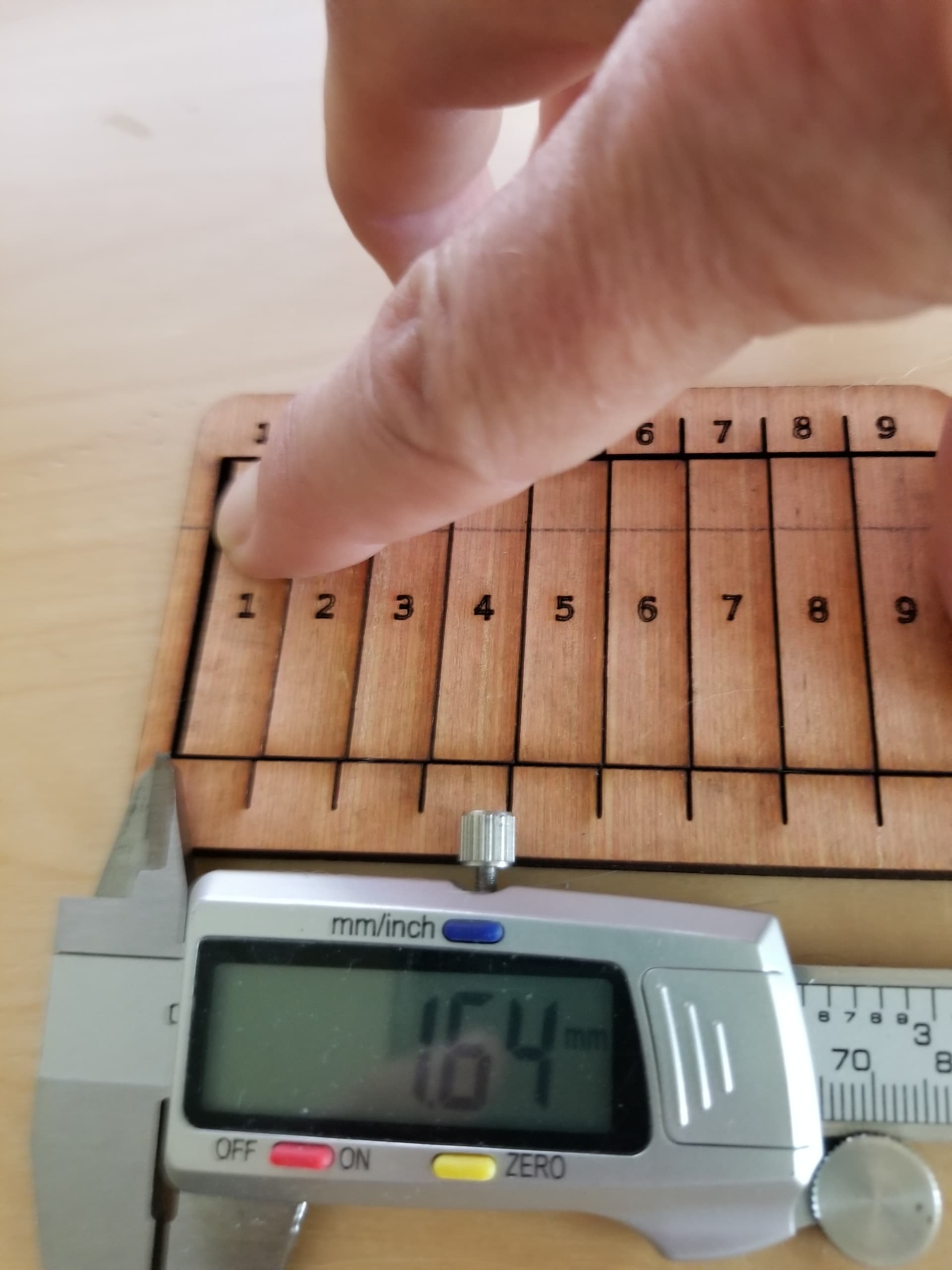
I don’t know if I was obscure in the photo of the kerf measurement. If you press them all together and measure the resultant gap. Don’t forget to divide by 10
I design it in a cad (freecad for me) and use parametric model parameters so I can change stuff around. I export it as a dxf file and load it into lightburn. I only use it for things that can get complicated in design, like finger boxes. I also like to be able to change a complex design by just changing one number, such as material thickness.
When I make my tabs and slots they are the literally the same size. Meaning if my kerf is correct the parts will be exactly like I specified. Since they are exactly the same in the dxf file, the will be exactly the same on the finished product. Having stated that, they won’t fit together since there is no clearance between the parts.
So, I did a little bit of lying, I do have a ‘clearance’ variable, usually 0.05 for plywood that is subtracted from certain parts for clearance of the joint.
Many of the ‘finger box joint’ programs that use kerf divide it by 2 and apply it to all the parts. Maybe because… keep in mind that, like the width of a saw is say, 2mm for simple math. So what’s the proper perfect kerf? If we cut down the center of the line we get 1mm taken off both sides of the cut. To get the proper offset we move the saw blade 1/2 it’s kerf. The same with a laser. I usually go to 1/2 if I have problems as an adjustment if the fit is too tight.
IMHO, the idea of a kerf cut is to get the exact size parts that are specified in the ‘engineering’ drawings. It’s not to adjust the cut, it’s to correct the mechanical for a proper cut.
This has been like practicing self dentistry - specifically a root canal.
OK where things stand right now. First off a huge thanks without the help I would have given up.
The problem is/was me. I didn’t realize I had to work with closed shapes, hence no adjustment with the many test cuts I made. 30 or 40 with small adjustments. The is a problem with my C01 layer - more in a moment on that. When I tried to duplicate the example above I used lines not noticing the pieces were rectangles, I am going to reconstruct that tomorrow, simply because I want to learn.
I mentioned above I had this working than I went in again and it didn’t work. That was because I changed the closed shapes which opened the shapes. I continued to use the open shapes with a huge amount of testing resulting in a total waste of time/material.
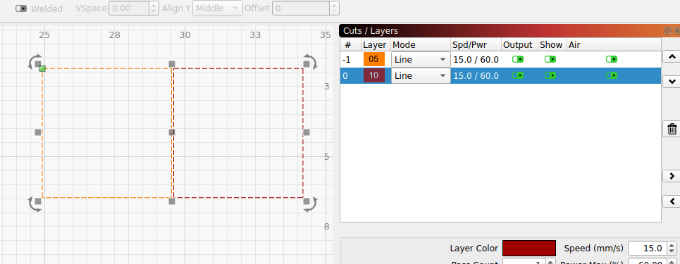
The acrylic I am using is 2.97mm, the kerf being 0.22 and the setting for each piece is 0.11 resulting in a very tight fit.
Some questions:
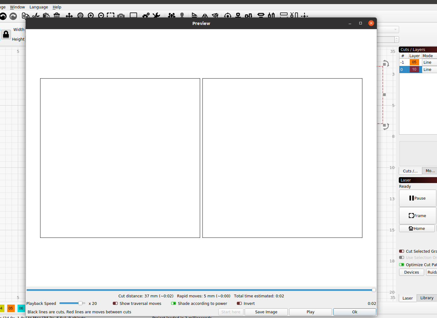
… If I combined both images on on 1 layer and set the kerf to 0.11 (1/2 of Kerf) would the result be the same as cutting on 2 separate layers with the setting at 0.11?
… Would the kerf work if I joined the two pieces as a single image with separation line/cut ending up with 2 pieces. The kerf setting would be set to 1/2 (0.11).
Lastly.
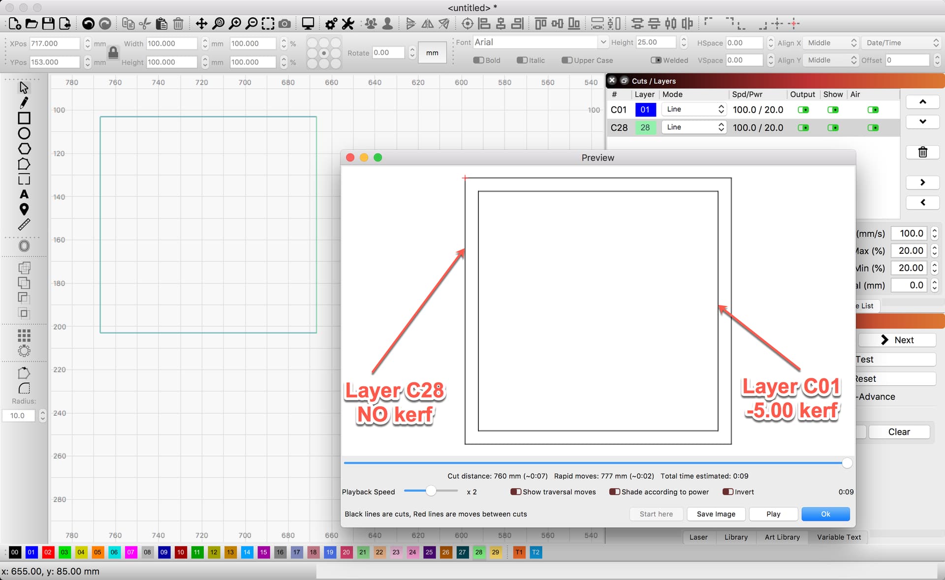
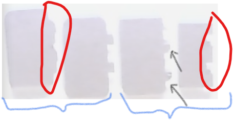
Problem with layer CO1. The odd shapes I showed above, rounded corners and tabs was caused by some setting(s) in my C01. Every rectangle I create has rounded corners when I preview the image.
Is there a way to reset a layer to LB original settings? It would appear I have set the current (wrong) settings to be default.
Again thanks.
It’s hard to hold the mirror, flashlight, and drill all at the same time isn’t it?
Yes. Same layer or separate layers are both fine as long as the kerf offset is the same on both layers.
I’m not sure what you’re asking here. Can show example or explain differently?
That’s weird. I can’t think of any layer settings that would cause that. What’s the radius of the rounded corners? Are we talking a few mm or some tiny fraction of a mm, or?
"What’s the radius of the rounded corners? Are we talking a few mm or some tiny fraction of a mm, or?
On this one I don’t think the resolve is worth the effort on this one. Last night I had changed some cut settings and can not duplicate the issue this am. Nevertheless, the following is to answer your question.
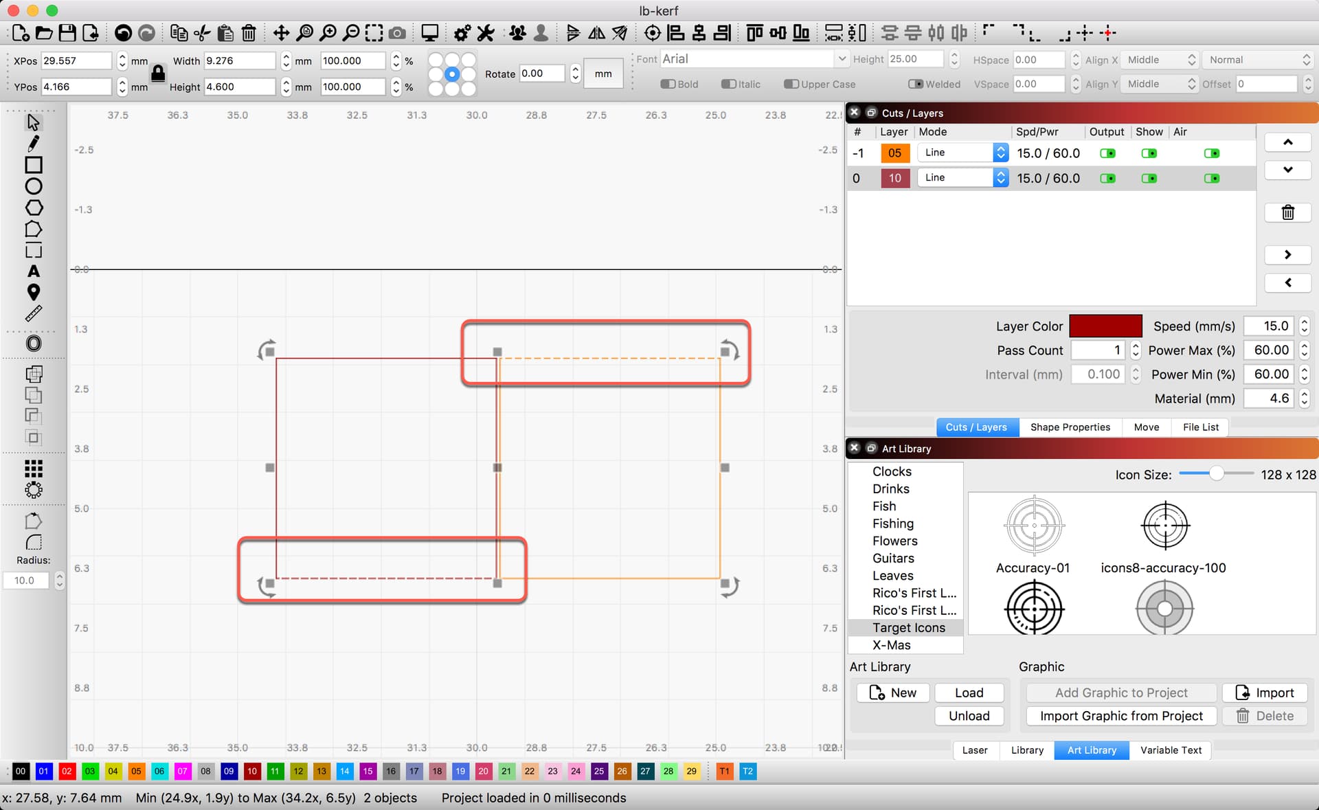
These pieces are 1 1/8" tall x 1/2" wide. No shape properties applied and I don’t think any radius applied at least not on the tabs or slots.
Blue 2 cuts different kerf set. Left Red & black arrows= rounded/deformed tabs. Right red= deformed slots. Using the C01 layer the shapes seemed to change as the kerf changed.
I’m not sure what you’re asking here."

 I did drop a line to tech support, they’ll get to when they can.