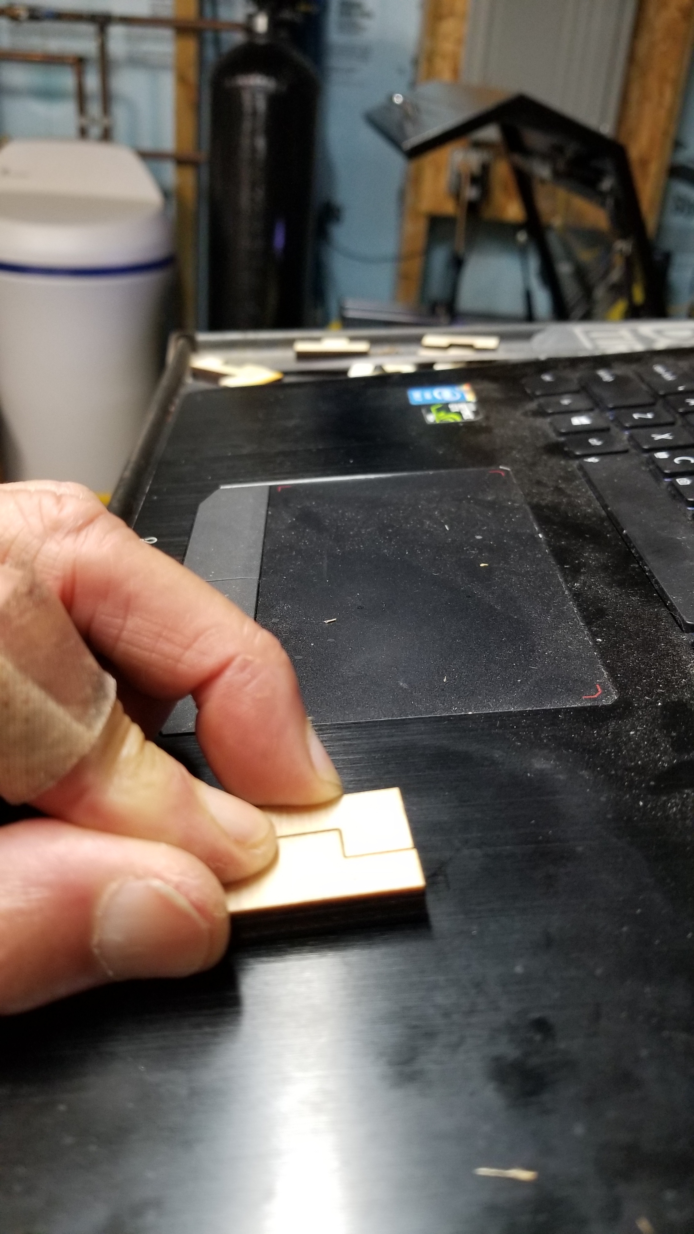
I cant seem to get my kerf offsets to work. I am trying to get my finger joints tight and regardless of where I adjust the kerf off set they are always to loose.
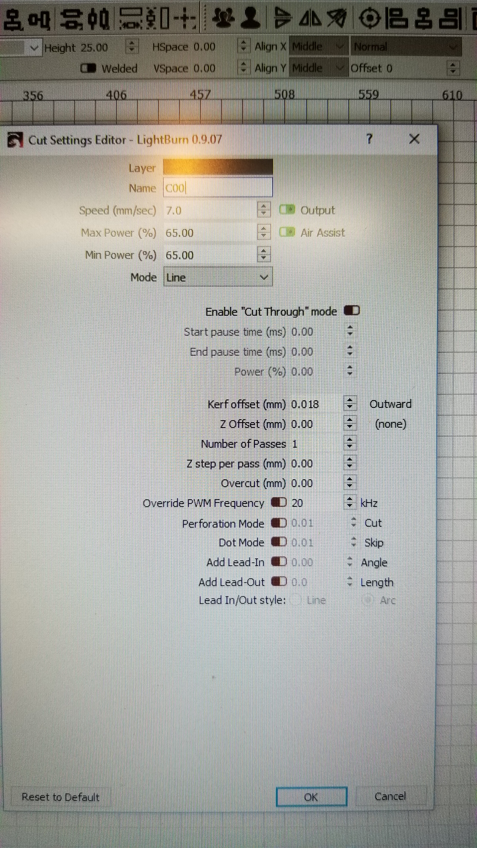
I cut a 1" square and measured the size of the cut out and the size of the blank. I came up with a .018 difference.
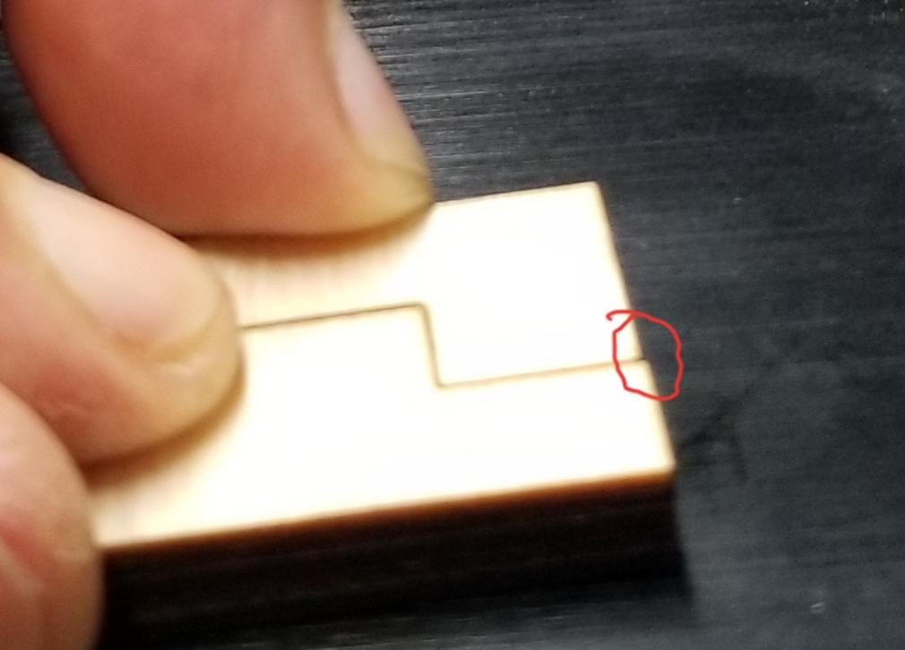
If I set the kerf comp to .009 the 1" cut out measured perfect. However when I cut the tabs out the gap is still to loose and doesn’t seem to change regardless where I set the kerf at.
Any help will be appreciated.
I am running a Ruida 644xg controller and the latest 0.9.07 firmware. 20191010_120249|281x500
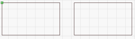
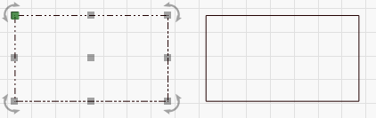
Are your shapes closed? If they aren’t, the kerf offset won’t work correctly. If you place the parts so they’re touching, you should be able to zoom in and see the offset visually, like this:
No kerf on the left, with a small kerf on the right:
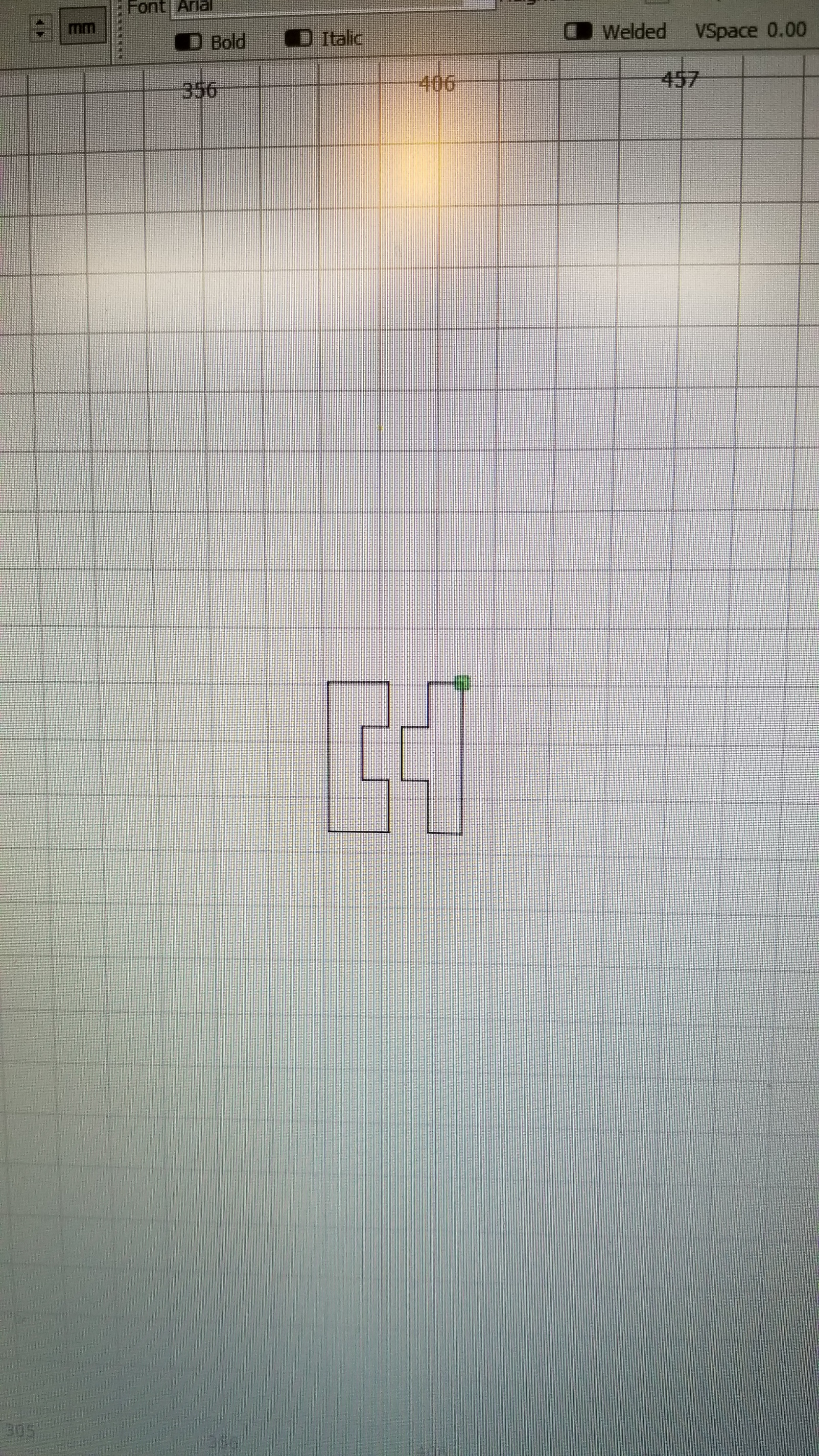
Both shapes appear to be closed. I am exporting from Fusion 360 as dxf. Importing into Lightburn and then resizing by 1000. The tab height is coming out to exactly 12mm as drawn.
OZ am I missing something when checking for closed shapes??
There’s a big difference between ‘appear to be closed’ and ‘closed’. These two boxes are visually identical:
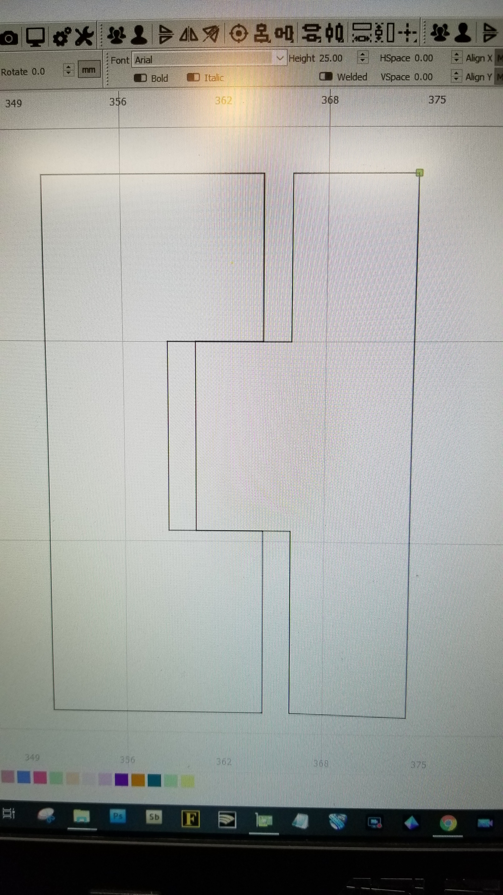
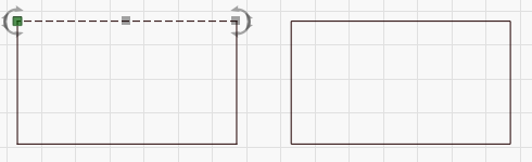
But the one on the left is actually just four lines, easily seen when I try to select it:
Since things are grouped when you import, it makes it harder to tell:
You can tell it’s grouped because it has a different selection pattern (dots and dashes instead of just dashes). If you ungroup it, you’ll likely find that the shapes are disconnected (DXF is notorious for this).
Select the shapes and run the auto-join tool (Edit > Auto Join selected shapes, or Alt-J) and that will likely fix it.
You never showed the ‘Preview’ window, which is where you’d “see” the Kerf Offset produced. This is not displayed in the workspace as that would be very confusing to edit and work with other objects that may or may not have similar settings.
Sorry @BobAbbott, but I can not figure out what you are showing here. Please post a clearer picture with a wordy description of what you want and what you are getting. I know you have been doing this but please, once more for my clarity. Additionally, I noticed the “matching” parts in the video you posted are on the same layer. Kerf Offset is a layer level setting and will be applied to all shapes on the same layer set to output. Could this be part of the issue you are having?
Rick you have probably found what I am doing wrong. So the matching parts should be on different layers and the kerf offset should only be applied to one layer…correct?
I wish I could just say yes. But that would be misleading other users as there may be times that this is the correct way to set up the cuts.
In your case, I think you will get what you want by placing one set of the matching parts on a different layer and apply the Kerf Offset to only one of the layers.
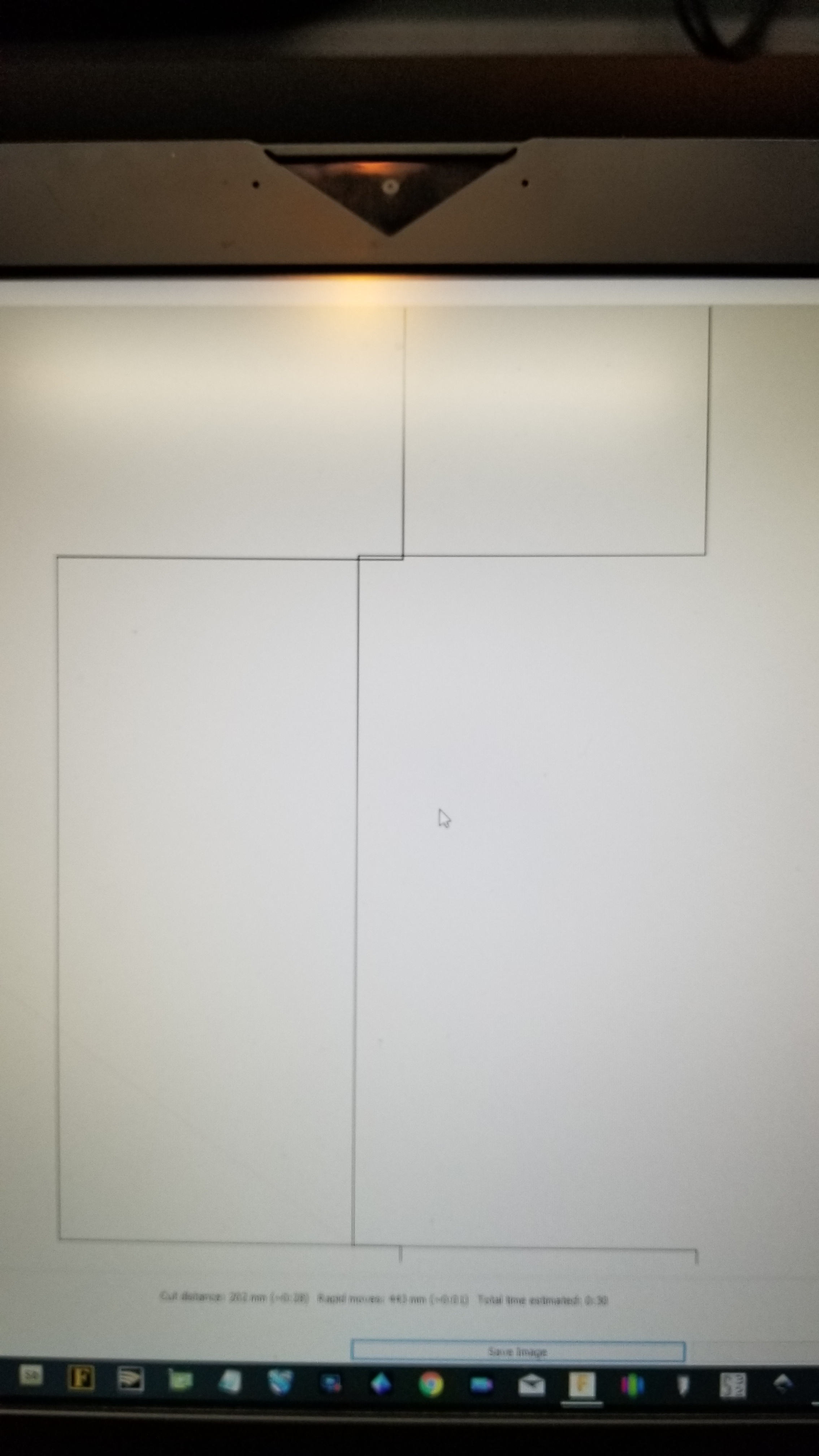
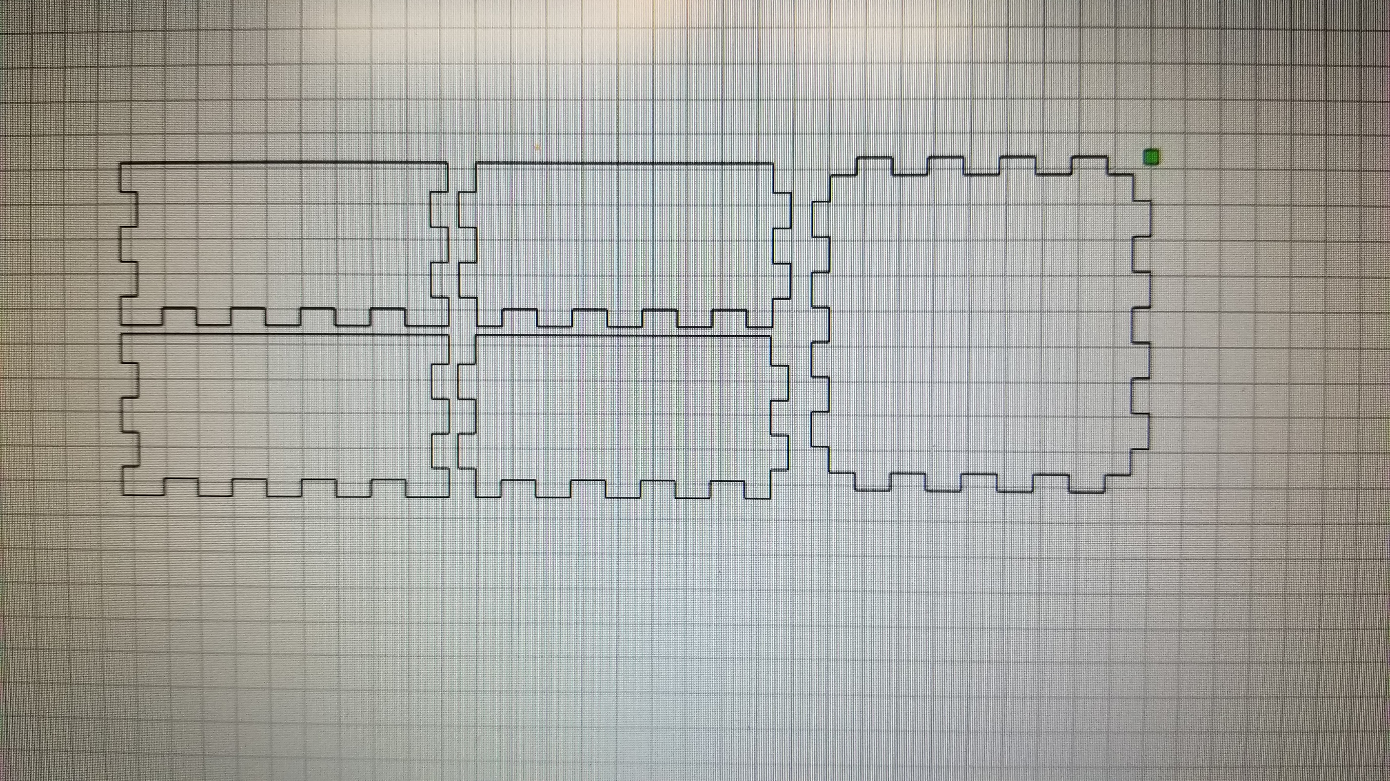
Ok…so with your suggestion of putting the kerf offset to only one of the 2 mating parts via separate layers worked for 2 parts. How is that going to work with this layout?
This all seems odd to me.
I’ve done a couple of small finger jointed boxes similar to Bob’s drawing above, and I’ve always used kerf offset on all the parts to make them fit right. If I need the gap to be .010" tighter between 2 parts, then I set both mating parts to .005" offset.
Why does the first drawing Bob shows only work right with offset on only one part?


