Laser not etching image, only outlines

Hello, I’m new here in the Lightburn Forum, so I’ll try to clarify my problem(s):

First, I have the Anycubic Mega Pro with laser attachment (1500mW), Marlin Firmware v1.2.9. I have been etching with only the sd card on bmp files for a while, and now the sd card reader on the machine no longer reads any bmp files. Have formatted to FAT32 twice. I think the sd card reader on the Mega Pro is kaput. So I got the Lightburn Software v1.2.04, on a 30 day trial. I have read the old forums related to this machine and problems to fix and one of them suggested using the Knutwurst firmware Marlin v1.4.4 (which i haven’t yet) and replacing M106 to G6…

Problem: I imported the bmp file (pendant 5) which is only a text image, simple. I checked the preview window how it will be lasered and it checked fine. Saved the gcode, opened notepad, replaced M106 to G6, saved again. Clicked run gcode which opened the saved gcode and instead of etching the words, it etched the outlines and the shadows around it. It looked like it was etching what the preview window showed as laser transverse movement instead of laser burn. In other words, i got white letters and black shadow outlines. Am i missing anything from the Lightburn software?

Please attach some screen captures of the Preview window in LightBurn.

Pictures of your project would be great!

You are also welcome to share the bmp file ( if the filetype isn’t allowed for uploading add .txt to the end of the file to circumvent the limitation)

The Marlin profile in LightBurn allows the M106 to work. Does the Anycubic Mega Pro require G6?

Please post other links or literature related to your Anycubic Laser Engraver that you’re working from.

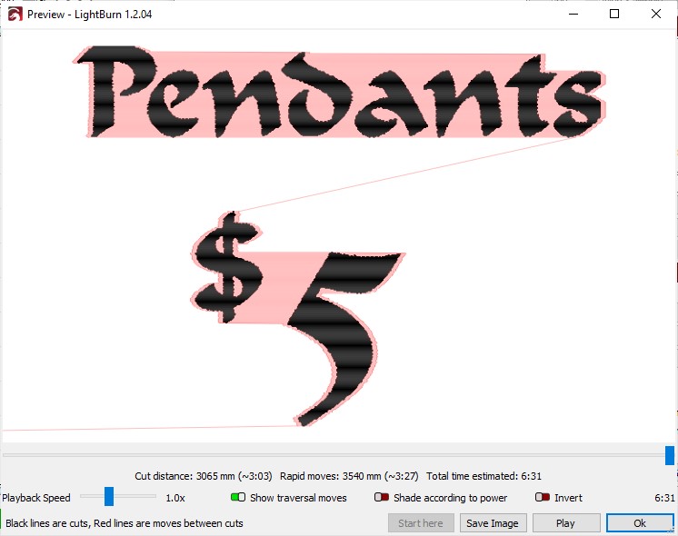
Here is the screenshot of the preview window.

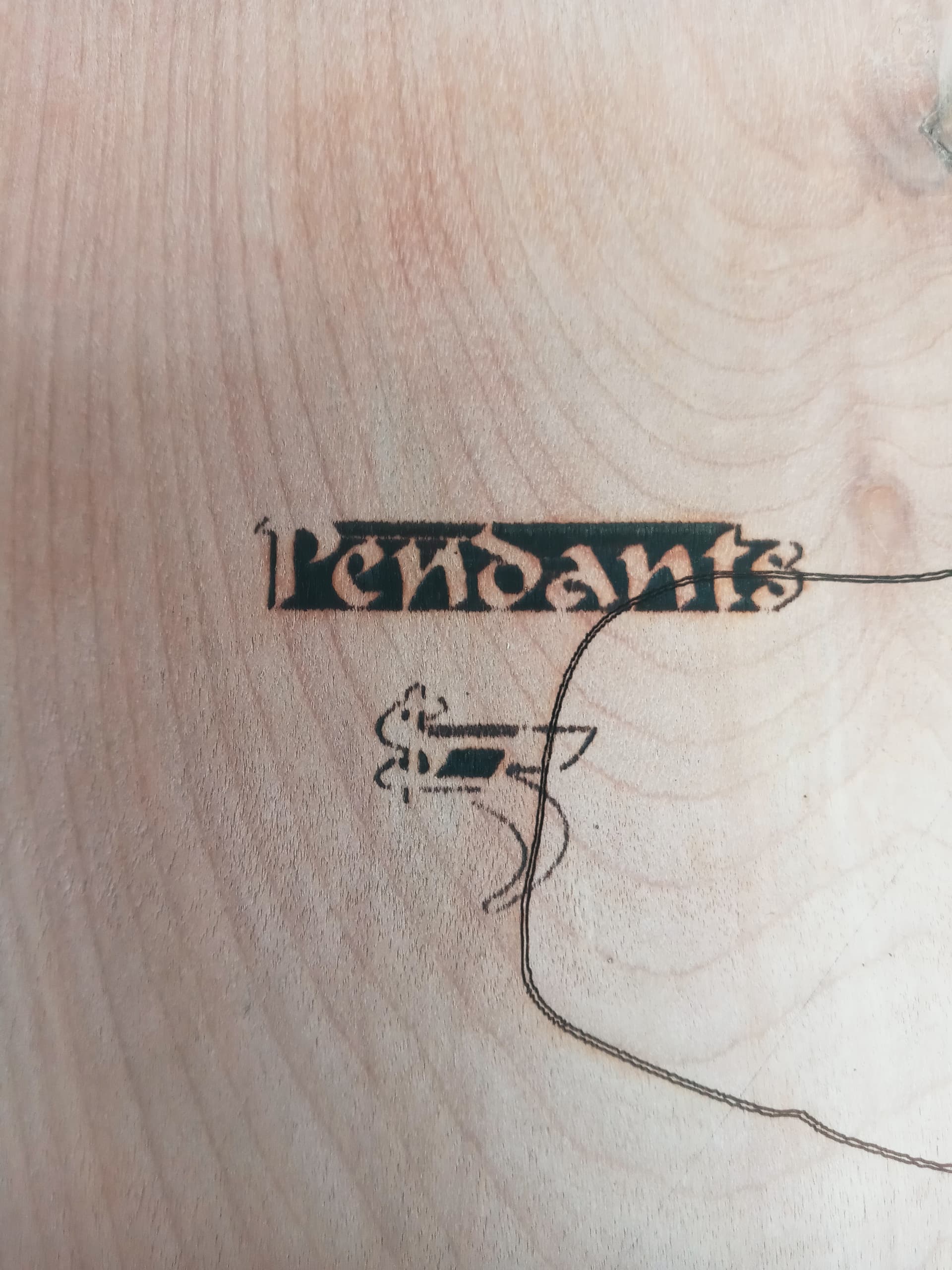
I also took a picture of the result from the laser etching.

As for the Marlin Profile, this one does not activate the laser, only the G6, (ex. M106 S0, replaced with G6 S0, meaning laser power at 0%) however one of the member mentioned that we have to add a G4 P0 before every G6 command, which is a time-consuming work.

The lightburn forum mentioned this situation on Any Cubic Mega Pro / Combo in Community Laser Talk created on October 2020. The owner/developer named Oz was part of the conversation. It was about 35 responses or so.

I found the link, read it, and edited your response to include the Hyperlink.

The most interesting part of your output is the two longer traverse (slightly diagonal) lines are not engraved. I imagine they are handled by the ‘fast whitespace’ traverse and acting correctly.

I agree that the horizontal scanning behavior is backwards to what was demonstrated in the preview window.

I see two Possibilities and one possibly missing test.

  1. The S0 through S255 are backwards, so the laser module is receiving an inverted PWM signal and making G6 S0 behave as full on (equivalent to S255) and G6 S255 is behaving as full off (equal to S0). The inverted PWM signal is not unheard of.

The recommended cure for this (the explanation, and how to invert the signal in the commented code) can be found here: Configuring Marlin | Marlin Firmware. If you have the source code it’s less work than the find and replace you’ve done so far.

  1. Intercept and invert the signal with a hardware hack.

Hardware Hacks that might work could include a chip to invert the signal or a reasonably simple transistor circuit to invert the signal Depending on how the laser is powered and controlled. A small stand-alone board to allow the spindle signal to be interpreted properly might solve it.

  • Test: Did you also test with M3 as an alternate Code to replace M106 or G6?

If M3 is enabled in your firmware you may have what you need. The Use of M3 is also in the Spindle / laser section of the Configuring Marlin Link above.

If you’re willing to share your GCode, I might see an easy option.

If the file resists uploading here, change the file extension to .txt and drag and drop or use the upload button (the up-arrow & flat desktop computer Icon / top middle of the reply box.).

I got the firmware v1.2.9 from Anycubic, which is a Zip file and after that, there was only one file, .hex and the hyperlink from the old forum that you just added, one of the members shared the source file, a .rar, which in turn has alot of .ccp, .ino and .h files. To tell the truth, I just learning.

The fast whitespace is at 7800 mm/min, but its still the same whether I turn on the fast whitespace scan or not. As for that number (7800), i was just following the instructions from another of your forum: Starting Step for Anycubic Mega Pro on Lightburn Software Questions. Of couse the program was from v1.0.06, so the new program i have has some additions that was not shown on Lightburn v1.0.06.

Me too. Every day. :slight_smile:

1 Like

I think I found out why it did the negative outline etching… Might have been the Image Mode set as Threshold on Cut/Layer Setting. I started fiddling with the Image Mode, tried Greyscale, since the laser is a diode, not CO2. It did etch the words without being negative, but not cleanly. I didn’t have time to add G4 P0 on every G6 commands. I did, however, added G4 P0 before every G6 commands on doing Vector outline cut with threshold on image mode because the G6 commands are few. The vector outline cuts came out well. After finding that out, I face-palmed myself. Although, i turned off the cut optimization selections, as it may or may not have improved that and i changed the bmp image to trace bitmap (for vector) and converted the bitmap again (for raster). I’d like to know more about those settings though. I’ll see if i can finish putting the G4 P0 before every G6 on notepad program and maybe show you the result…

Ok, I figured out how to quickly implement the G4 P0 (dwell/ms i think) on the notepad. All i had to do is type:

G4 P0
G6

And then select the words and copy for future paste. Go on Find/Replace, Find M106, replace all G6, and find all G6 and simply right click one of the shaded G6 and paste the G4 P0 G6 i showed on above, and on lightburn, run gcode and click the file that was saved. I tested 2 image modes: Jarvis and Greyscale and this is the result with the G4 P0 commands before every G6 commands.


A phone screenshot of the Cut/Layer Editor result:

This is the image of a result without the G4 P0 on Greyscale Image Mode:

Although on the jarvis and greyscale with the G0 P0 added, the lines don’t seems to be clean on the edges, i might be missing something here.

By the way, is there a tutorial for this program, lastest version, in pdf?

On the main doc page:

You’ll find the download link for a 241 page PDF:

Which seems current through V 1.4, so I think they’ve got it covered.

I downloaded that. There seems to be a problem on page 84 about “Image Mode”. They are cropped and doesn’t show the full information.

Looks like the PDF conversion can’t / didn’t handle the gallery in the HTML version quite right:

Seems like you should file a bug report on that …

Exactly how do i file a bug report? I’ve never done this before on this forum

The most straightforward way is by email:

support@lightburnsoftware.com

Or, since @JohnJohn has been around, this mention should pull in his eyeballs again. :grin:

1 Like

@ednisley I am around…

@Vanilar23 I see it. I have passed this information and links on to the documentation team this morning. If you have emailed support, I’ll gather that too and add it to the process. :slight_smile:

I just emailed the problem to Support, JohnJohn, and i don’t mind that you inform Support about too.

I just read something internally, letting me know that the issue has been found / resolved and it moves to final review soon.

Also, is Oz still around? Haven’t seen any new forums related to Mega Pro

This topic was automatically closed 30 days after the last reply. New replies are no longer allowed.