I think you stated you work with wood. You mark a piece of wood with lines that are 16 inches apart.
If you ‘cut the line’ the board will be ‘short’ by the blades kerf. 1/2 of the kerf is used at each end since you are cutting the line, half on the ‘scrap’ side and half on the ‘good’ side for the complete width.
The only way to get a 16 inch piece is to align the one side of the blade to cut ‘on the line’, adjusting where the cut starts to eliminating the error caused by the kerf. This done at each end, gives you a full 16 inch part.
Where is comes into play is that you can have a ‘tab’ and a ‘hole’ that are designed exactly equal in size. With no clearance, they will NOT fit. Generally I found that 1/2 kerf on each part works well.
There are some problems that you should be aware of as @berainlb noted. I commonly do something that part ends up larger than the machine can handle.
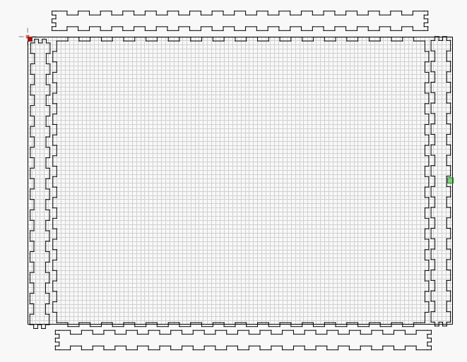
I have a stereo cover I made for a friend that is a bit larger than the laser bed.
The complete design generated by the box generator. I only want ‘joints’ at the corners to prevent it from sliding off the stereo.
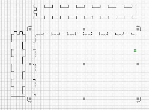
For the application, I only need the four corners and they are symmetrical.
Only one corner is needed…

The large ‘open’ shape (selected) will not allow you to apply a kerf. I adjust the other parts to make up for the lack of ability to apply the kerf. In this case it’s not that big an issue, but if more than one part is open, it makes things difficult.
The shape has to be closed so the software knows ‘inside’ from ‘outside’. It would be nice to be able to tell it which side to apply the kerf.
When I cut it, I put it in with the front/left side of the part to the back/left and make the cut, then flip it horizontally for the right/back. Then flip it vertically for the other two ends…
Good luck…
Hope I didn’t confuse you even more… 

