@Rick
My application is tracing plans for model aeroplanes I download from the net, a pretty basic process. Tracing shapes in FB always produces two lines which consist of multiple segments. Selecting all unwanted segments and deleting them is a time consuming and onerous task. I also find that the traces often include spurious spikes and gaps and other bits that shouldn’t be there, as the plan may have parts drawn over the top of other parts, or text may appear across the middle of a part, or there may be gaps in the lines for no apparent reason. The plans may also be quite fuzzy, (especially if they are old plans that have been photocopied) around joints for instance, which causes problems with tracing. Also, text on the plan is traced which I don’t want for cutting, so it has to be removed as well.
I have found that it is quicker for me to manually trace the parts I want using a CAD package, and produces a better result, as i can often improve the quality of the plan (or part) to remove slight deviations or imperfections in the original, and at the same time use fewer segments (lines) for each part. I find I can draw circles and curves more accurately than trace will draw them, and ensure lines that are supposed to be parallel, normal or symmetrical are, in fact, parallel, normal or symmetrical.
I get that tracing works quite well for some applications, but I have found that for me, manually tracing works better and requires less effort.
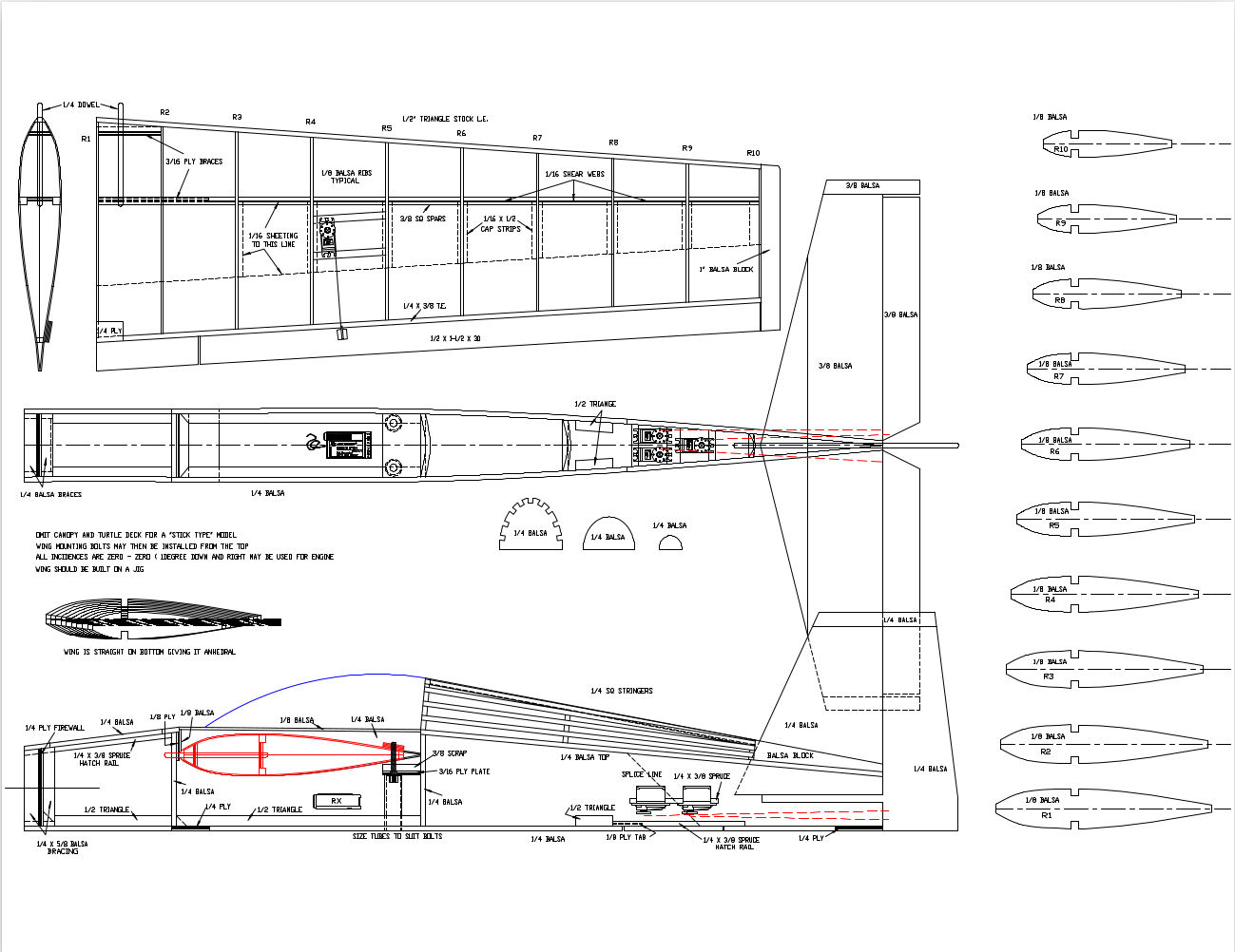
I’ve uploaded a couple of plans for you to have a look at. I haven’t tried tracing the Corsair as I was pretty sure it wouldn’t work properly, old plans like this frequently have the grain of the balsa indicated by the multiple short lines on the part, which would also be traced and take forever to clean up. Ditto the wavy lines to indicate a ply part. The Ag120 is a more modern plan that I suspect was created with CAD so may be more amenable to tracing. Enjoy.
If the intent is to generate a ‘cut-ready pattern’, then I can completely understand the requirement for significant editing to produce usable paths, using any commonly available tracing software, from these examples, yes.
A challenge I can not solve, I must admit. The source is the source of the issue here, making tracing a less reasonable solution in this case, correct.
But to say, “It hardly ever provides a usable result…”, I had to try. There are many instances where ‘Trace Image’ produces fantastic results. It all depends on the design goal. Case-sensitive.
I have your top drawing copied and loaded into LightBurn. The miserable quality / resolution means that I do not even bother to start a trace attempt. It should be fair to judge a feature or tool. If your image is scaled up to 1:25 ???, you will not even be able to saw it out with a good band saw with a usable end product as a result. Drawings in this resolution will always require a lot of extra work. But if you find proper drawings, you could save a week’s work on such an aircraft model.
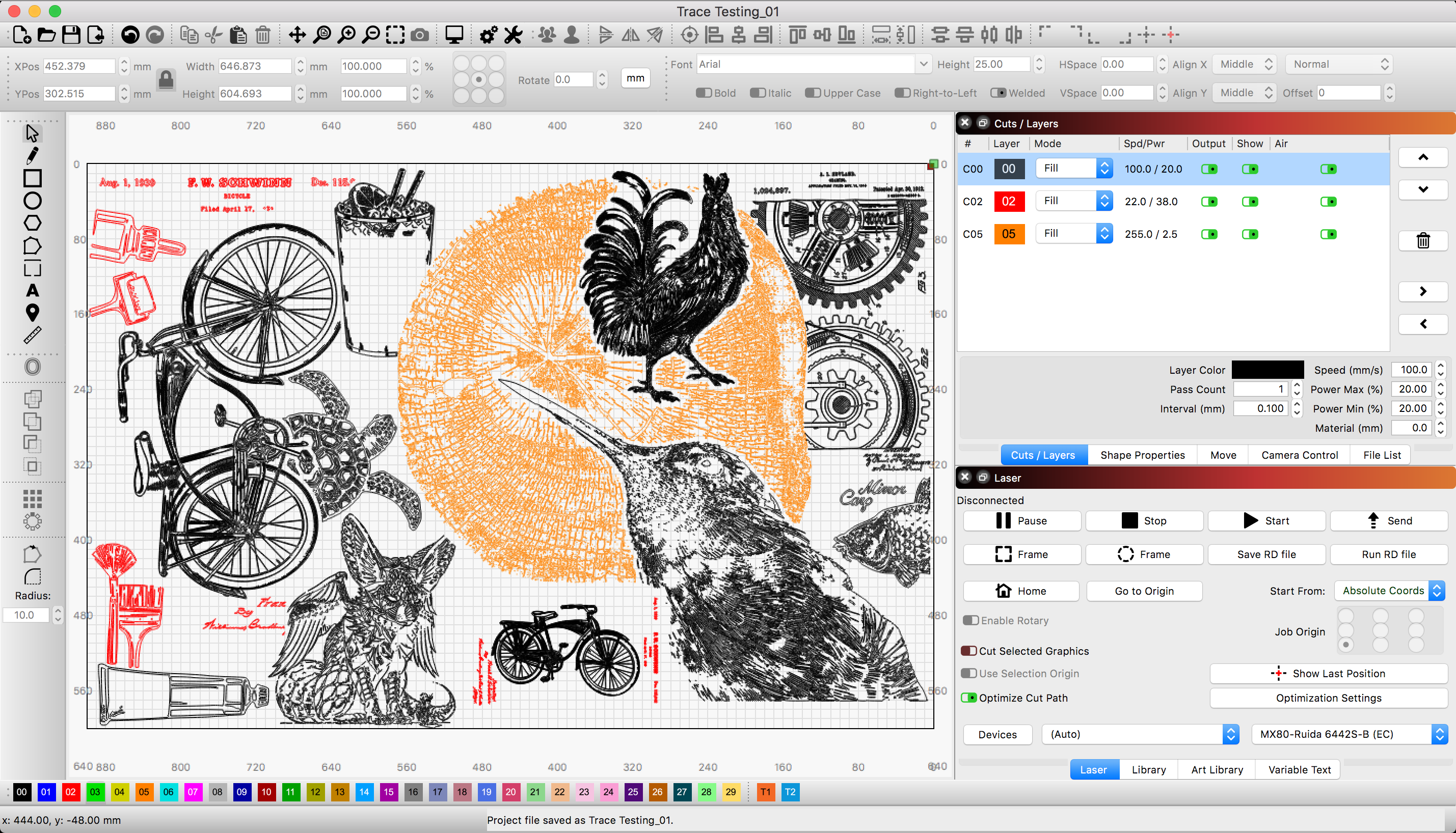
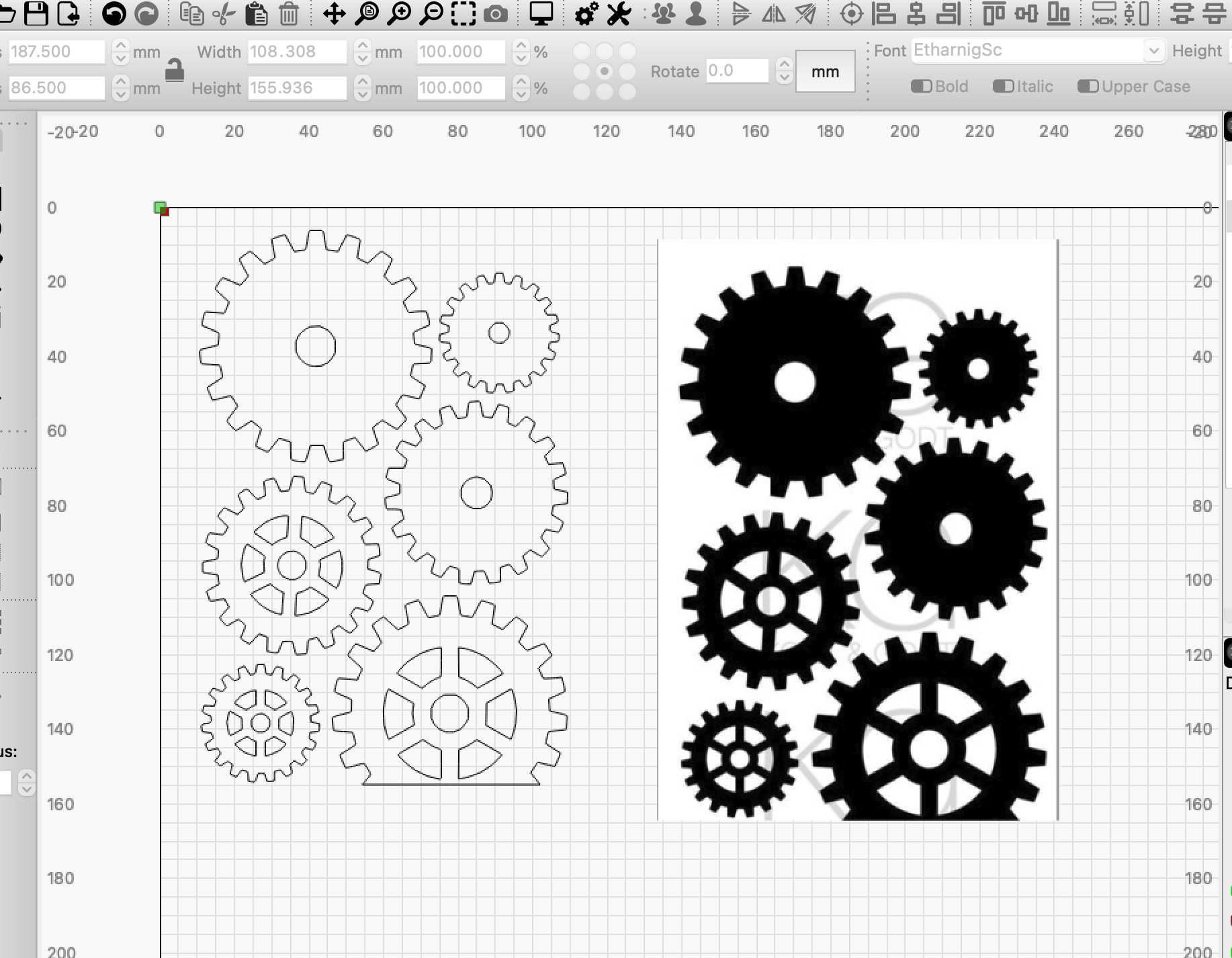
In my example, from finding a random image on the web until I posted it here, including text and small test in google-translate, it honestly took me under 5 minutes. The best thing is, if I trace and cut out my gears, they are ready to use! (without extra work)
It is about using the right tool for the right task.
It’s not a religious war I want to start, certainly not, I just think it’s a shame that people can not get the best out of the things that are available.
@Rick
Fair point. I withdraw the “hardly ever” comment, or perhaps I should qualify it to “hardly ever produced results for my particular use case at my skill level and knowledge level that I was happy with.” I apologise for any perceived slur on your fine product, none was intended.
I tried it again in FB, and found that @bernd.dk’s comment is valid. Scaling up from the screenshots of the plans is never going to give a perfect image for tracing, pixellation will ensure there are always going to be wobbles and anomalies. There will be some cases where it will give a good result, for other cases it’s back to plan A, manually tracing the part.
RalphU, I wrote that it honestly did not take me 5 minutes.
I cut and pasted a random image into LightBurn and traced (all gears together) with the basic settings almost unchanged. When the objects are so finely delimited and the lines are intact, and if it is even a “fill” subject, it takes no time. The cut gear should only show that it is a simple cut and paste. You have already had to settle for a screenshot of a copy.
@RalphU you got it in one, Ace! Retired too, and loving it. I also have to confess to enjoying the process of manual tracing, I find it almost meditative, so for me it is not a chore. And, as you correctly state, drawing parts with precise dimensions is a requirement for them to fit together properly in the final product.
With many of the plans I work with the parts are often drawn as an approximation, and given that some (most?) were originally hand drawn, inaccuracies are inevitable. In the old days you transferred the part onto the wood to make the part (usually with a pin) then cut it out and sanded it to approximately the right shape, then modified it until it fitted properly where you wanted it to go, so the final part could be quite different to the drawing. So the part drawings were more like guidelines that precise shapes.
Today it’s possible to draw the parts with CAD and make them exactly the right shape to make them fit precisely where they are supposed to fit, then cut them out precisely with a cnc cutter and everything just clicks together! No sanding, no shaping, no slicing fingers with sharp blades, no blood all over the plan. Brilliant!
I agree with @bernd.dk though, that if you have a good source drawing, LB’s tracing function is extremely accurate and easy to use, and produces excellent results. It certainly works very well on images that would be impossible to manually trace, as in the examples @Rick has provided. But as he also mentioned a lot depends on the quality of the source image. If the quality is poor no tracing tool is going to work satisfactorily.
In my case, scaling up drawings from screenshots, pixellation is always going to be an issue, and drawings I’m trying to trace will always be average at best. So, for me, if I can use LB tracing I’ll use it. If not, it’s back to the drawing board!