Also should list the bed size a little smaller? Mine is 1200 x 900. Maybe go 1190 x 890.
Not sure what you mean by that?
Depends on your machine. If you have mechanical limits at 1200 x 900 then it is wise to make it a little smaller, yes.
Can I put a jumper from the X- connection to the X+ connection and the Y- connection to the Y+ connection. I think that is the way it was on the Leetro board.
Thanks for the help,
Bruce
That means you are using the negative limit switch also as the positive limit switch? Why would you want to do that? If you do this, reaching the - switch will also trigger the + switch, probably resulting in the machine not being able to move anymore since both limit switches will be activated at the same time.
Maybe we should get back to the start. What are you trying to solve now? You spoke about the machine missing steps when hitting mechanical limits and in the old situation stopping because of losing steps and now we are at the point where you want to bridge limit switches, trying to solve which problem?
I’m not sure. I haven’t had a chance to go fool with the laser for a week now. I just don’t want the laser to accidentally run into a side rail and sit there and rattle while try to hurry up and hit the estop. I just have not seen any wires for other than the white and orange wire.
I am going to try and home the laser and also go through the settings tomorrow.
Thanks for all your help!
Bruce
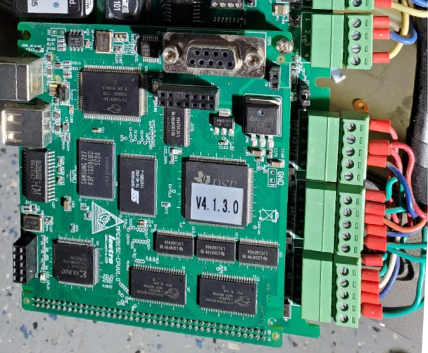
JP, I have most everything working pretty good except for my limit switches. I will try and explain where I am with pictures and some text and see if you can figure it out. I hope you have some patience with me. Here goes… the first picture is the pin out of my Leetro board
Ok. I am having trouble how to post pictures

Here is a picture of my Ruida control with some wires hooked up to the limit switches.The X and Y limit switches work some what.
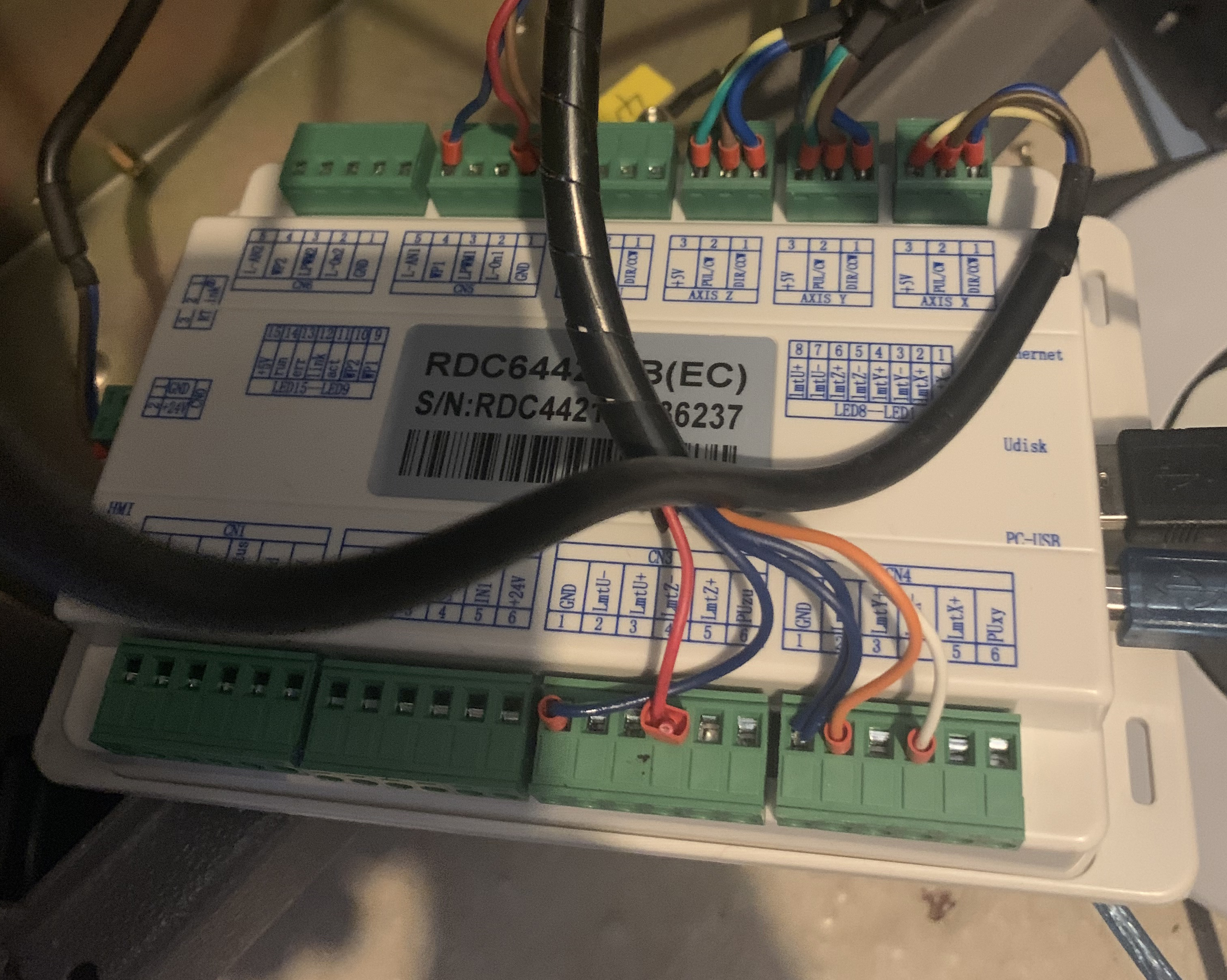
These wires were left on my old Leetro board. I wasn’t sure if they were used.
Thanks for all your help and patience!
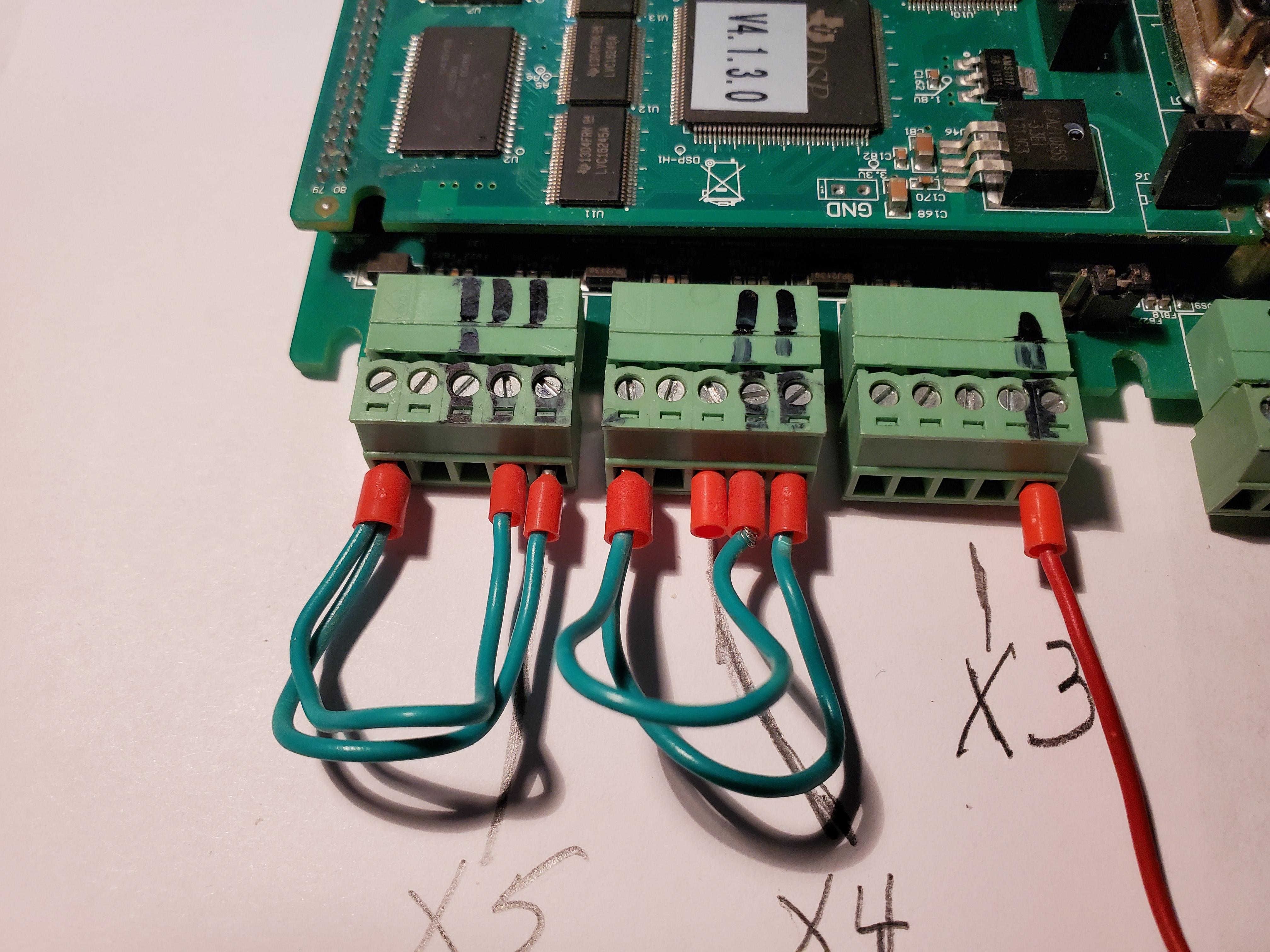
The limit switches on the Leetro board are X3, X4 and X5
In the picture above the red wire is in pin #1
Sorry for not coming back to your earlier. I had a look and as far as I can see your limits were bridged on your old setup. You have a connection from pin 5 to pin 1 and 2 on X5 and X4. Pin 5 is +24V and pin 1 and 2 are the min and max limits. Could it be that you had them disabled in the old setup?
Here is a diagram for connecting the wiring to the Ruida controller:
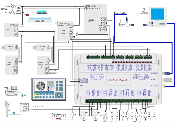
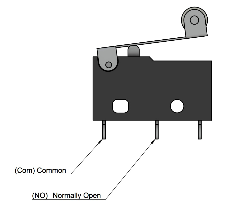
Basically run a wire from GND to your limit switch and then run a wire from the limit switch to the ruida controller. Make sure that you pick the right pin of the limit switch if your switch has two output pins. You can eather look up the type number in Google for an indication or use a multimeter and set it to beeper mode and figure out which of the pins connect to the common pin.
You probably have something like this:
Ok, JP I’ve run a ground wire to the X and Y connection on the Ruida controller. Then I can find the normally open connection of the limit switchs. Do I hook this wire up to X- or X +, then same thing with Y- and Y+ where does the xtra two wires come from?
How many limit switches do you have? You have to connect at least the two limit switches you require for homing your machine (x and y axis). You can find out by checking in which corner your machine wants to home. Then connect these two to - I believe. Keep your emergency stop at hand for the case I made a mistake and it should be + 
JP, I have two limit switches. One on the X axis and one on the Y axis. I already have 2 ground wires for the X and y limit switches. No I need two wires for X minus and X plus. Then I need two wires for Y minus and Y plus. I have an orange and white wire hooked up to the minus side for X and Y. If I close either limit switch a red led on the Ruida control lights up. I will chech tomorrow when I get home to see if these two wires go to the limit switches.
@jpjacobs, JP, I have two limit switches. One on the X axis and one on the Y axis. I already have 2 ground wires for the X and y limit switches. No, I need two wires for X minus and X plus. Then I need two wires for Y minus and Y plus. I have an orange and white wire hooked up to the minus side for X and Y. If I close either limit switch a red led on the Ruida control lights up. I will check later today when I get home to see if these two wires go to the limit switches.
Think we are in the same boat. My platform shifted off to the right about 2" so i just found out. no limit switches i dont belive; as they are wat looks to be nema step motors. just need to figure out wat the password for the system would be as it had a frame preset in it. cant replace it at the moment as the system is password protected, how ever the password did not stop from deleting the the presets. have reset manny times and made a new file but “templeate is there with no rear visual” any sugsetion?
RD8888
Set factory Param: CC8888
Default: HF8888
This topic was automatically closed 30 days after the last reply. New replies are no longer allowed.