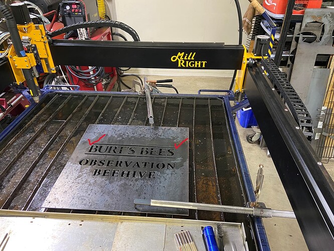
Print and Cut is awesome, I used it the other day to cut a design that is much larger than my CNC workarea. 3 stage Print and Cut job w Plasma process . However, there is room for improvement in this use case that I applied Print and Cut to solve. The problem is that I cannot “see” or examine the margin of error in registration before the cut. What Print and Cut does not do (as far as I know) is it doesn’t give a pre-cut visual of the post registered laser positions in the workarea, and in the absence of this feedback I don’t have a sense of any margin of error that I may have made during the manual alignment/registration of the laser pointer to the cut material. So, I played around with another method to register cut material randomly laid in the workarea to my LB design sketch and cut shapes, a method that does give the necessary visual feedback to check for registration error before the cut. The LB tools to use are a combination of: the recently added “Two-Point Rotate/scale”, and “Move to Laser Position”. The process is similar to “Print and Cut”, it involves registering 2 points in the workarea with the laser pointer (or mechanical pointer in lieu of plasma jet for my machine) and making those points coincident with 2 points of the LB design shape or sketch.
The process steps are as follows:
Use Absolute origin mode in the laser window.
- physically locate the first piont in the workarea with the laser pointer (be sure to have “Show Last Position” ON in the Laser window). A red dot and crosshairs icon in the work area of the main LB window will indicate what LB believes to be the laser position. If you suspect its not reflecting the correct position in the window, click on “Get Position” in the Move window to refresh it.
- select the LB design shape that will be cut (first stage) or that has been cut (subsequent cut stages).
- snap the design shape to the laser pointer, using the tool “Move to Laser Position”. This tool locates the active “handle” of the LB selected shape to the current position of the laser pointer. The active “handle” selection is made on the tool bar, its the square of 9 radio buttons, representing the 8 selectable points on the perimeter of the shape and the 9th being the center. If a handle is not on the point of the shape that you want to locate to the laser pointer, no problem, just grab that point and drag it to the laser pointer. Ok, the first point registration is done.
- physically locate the second point in the workarea with the laser pointer
- select the same shape as in step 2.
- use the “Two-Point Rotate/scale” (but don’t scale) tool to rotate the selected shape to the laser pointer. The shape point will land on or near the laser pointer. Bingo! If not landing on the laser pointer, then you will see the discrepency between it and the shape point, and be able to measure it. Change your grid spacing to 1mm for best accuracy, zooming will get you to 0.1mm micro grid. This works well because the second shape point is forced to travel on the arc/radius established by the first point. Now you can visually see the accuracy of your (twice) manual registration of the laser pointer! If the margin of error is not suitable to you, then make the necessary registration adjustments as needed, the manual registration of either or both laser positioning points is in error.
I found this method to be much easy on my nerves than waiting until after the cut to see my margin of error ![]()
Cheers,
Lou
