Mirror alignment tool

HAVE ANY OF YOU GUYS USED THIS TOOL?https://american-photonics.myshopify.com/products/k40-reverse-laser-alignment-nut
JUST WANTING TO KNOW IS IT WORTH IT.

1 Like

I have and i love it if i had it earlier it would of saved me countless hours of pulling my hair out.
I now have a tool that will always be with me for mirror alignment. I tried aligning the forward way and had no luck. my hot end was way out I loosened up the linear guide bearing that attached to the nozzle push it in and everything was somewhat aligned now just fine tune… I used the reverse method and it showed me what was going on and it made mirror alignment so much easier. Just my 2 cents…

I just 3D printed a nozzle inser for a laser diode to go backwards along the optical path to see what it’s all about. I tried doing the same thing from the tube end a while back, but couldn’t get a good coaxial alignment.

The only problem with aligning the beam backwards is that if you are off, you either have to move your laser tube, or guess at the amount to move your head and start all over.

The biggest misconception in laser alignment is that you have to be centered in everything, not true. Yes in a perfect world you want to be dead center, but oh well.

You get as close as reasonable to center in your Y and then X, and finally Z while making sure it is PARALLEL. Parallel keeps everything in the same spot as your gantry ( Y and X ) and work bed ( Z ) move. Once you are parallel all the way through Z, then you get it centered in the lens tube to hit the center of the lens. And that does NOT equate to hitting the center of the hole into the #3 mirror. With the high quality of engineering in many of these machines one is not linked to the other in any way. Personally I hit my #3 about 2.5mm high to hit the center of the lens tube.

1 Like

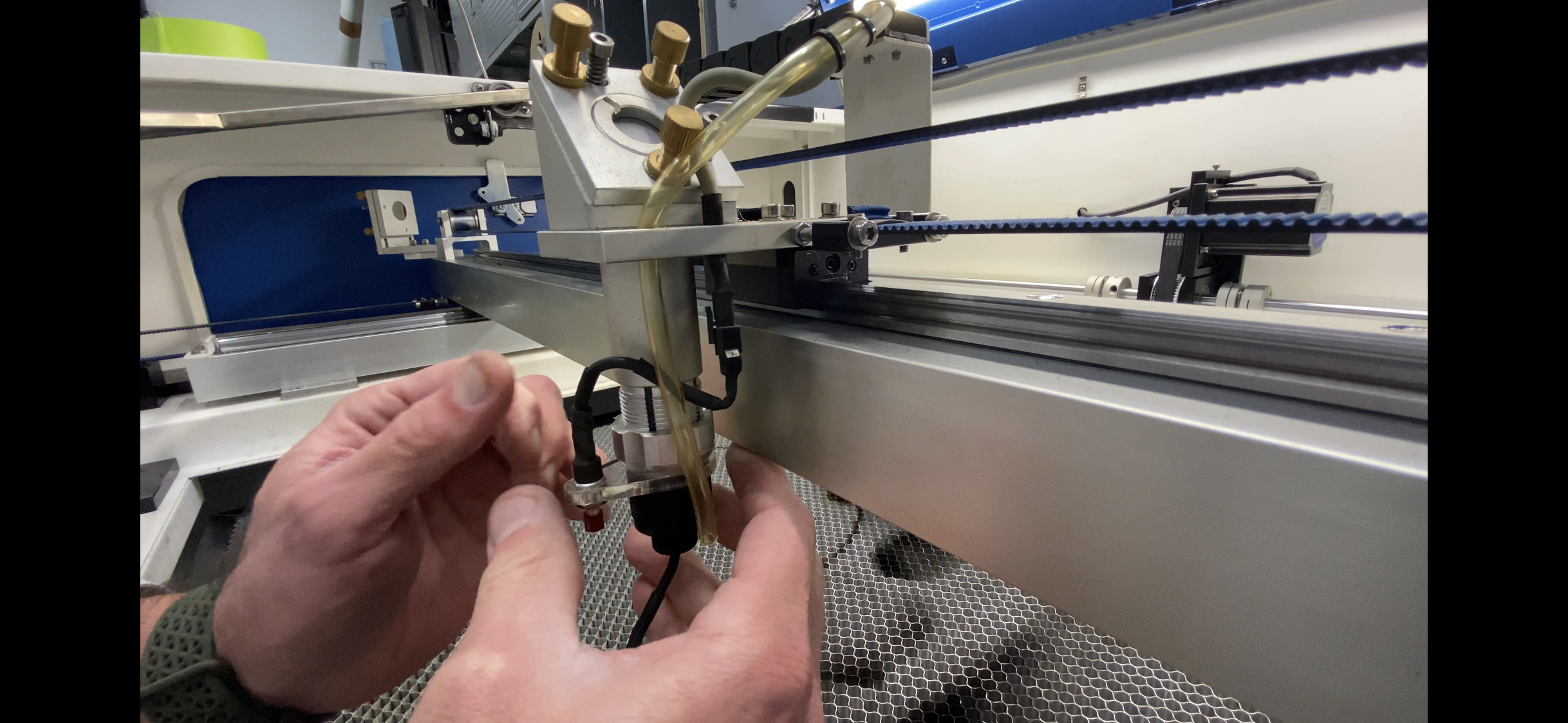
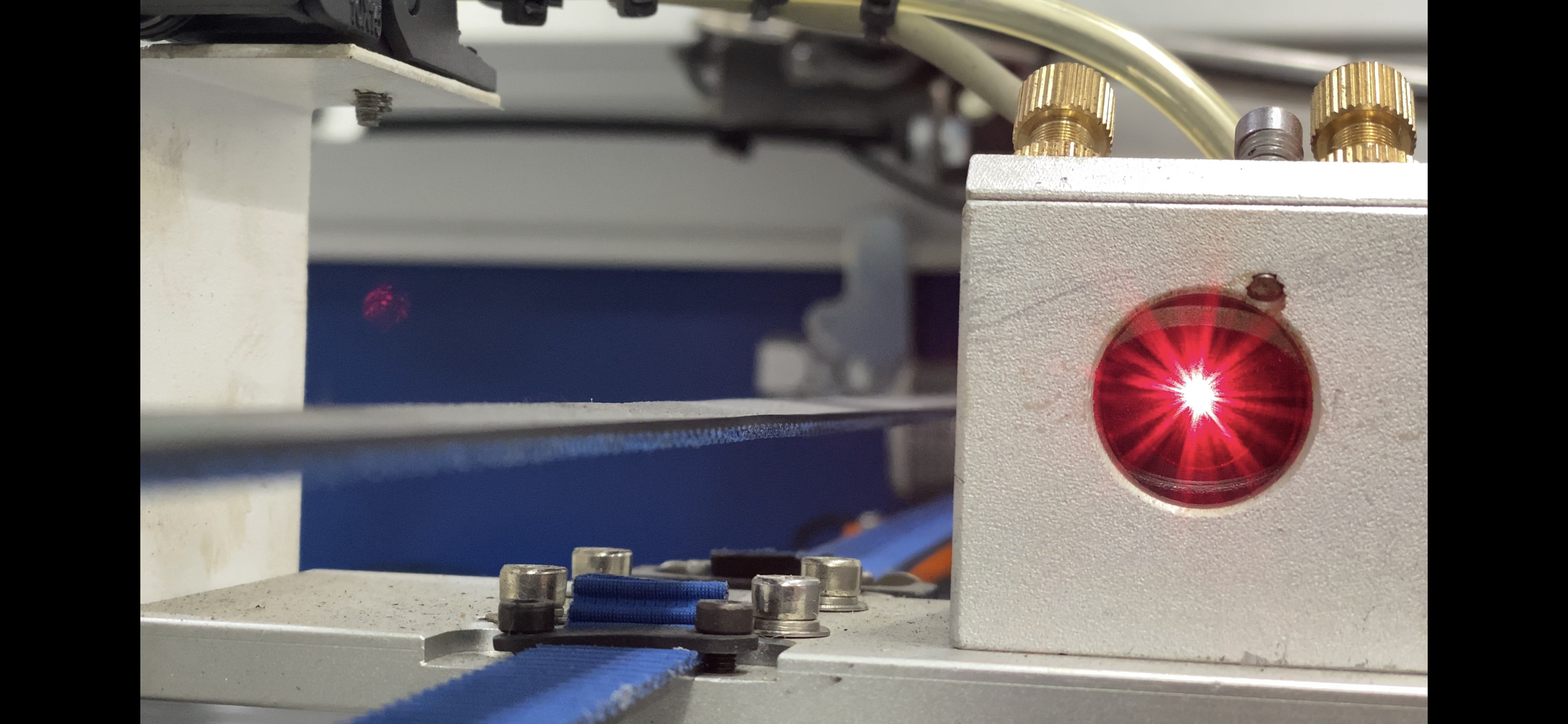
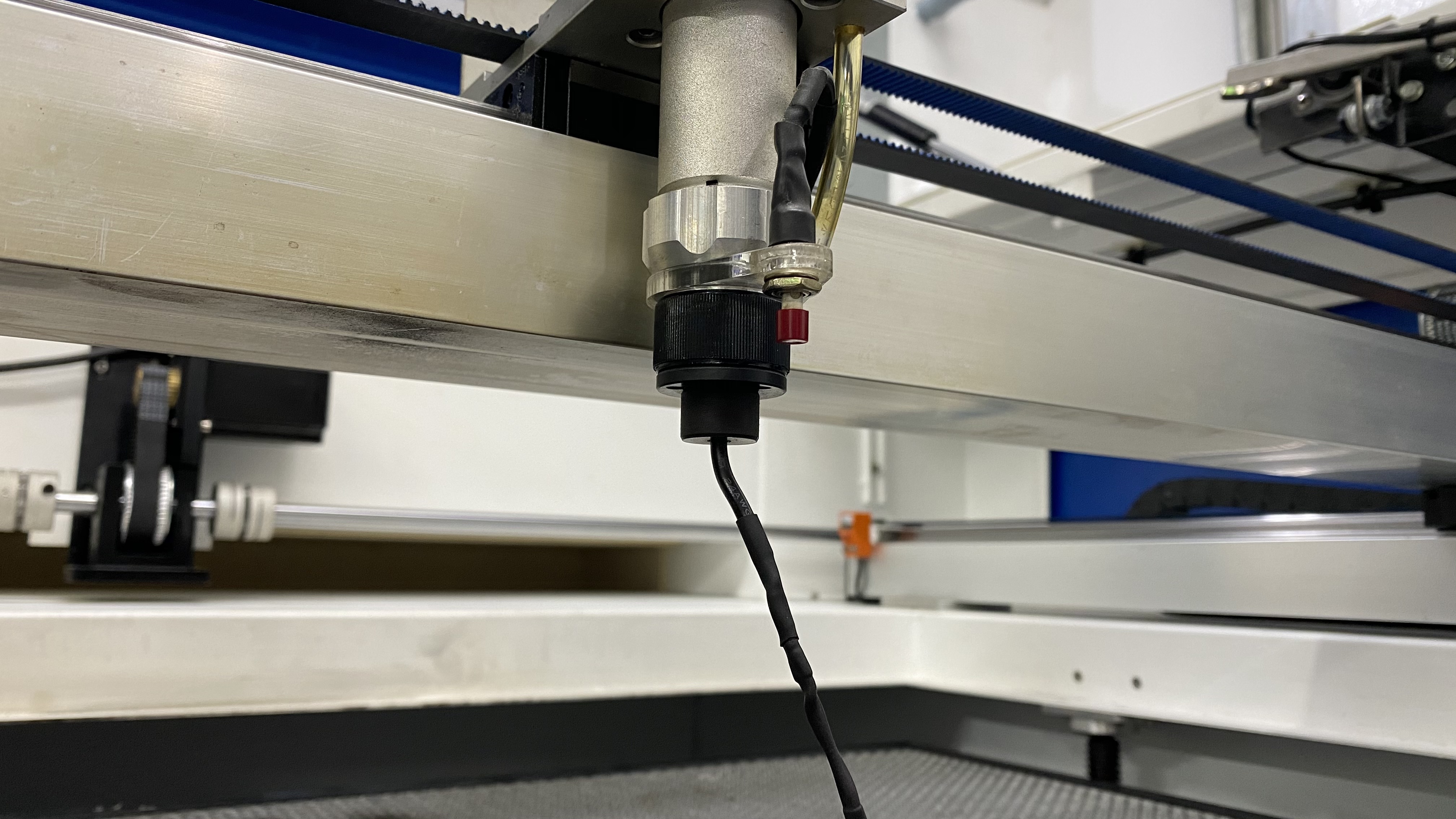
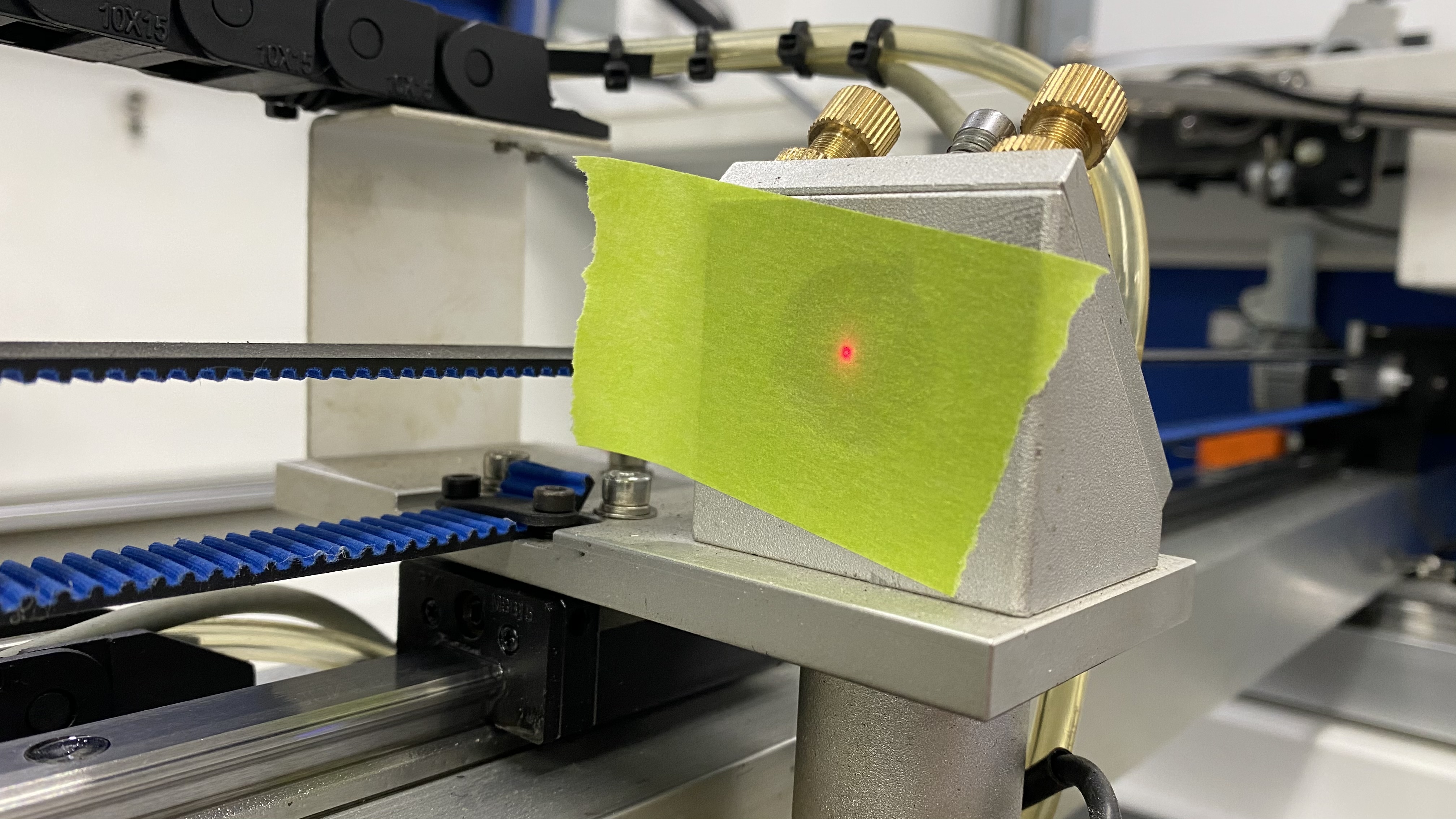
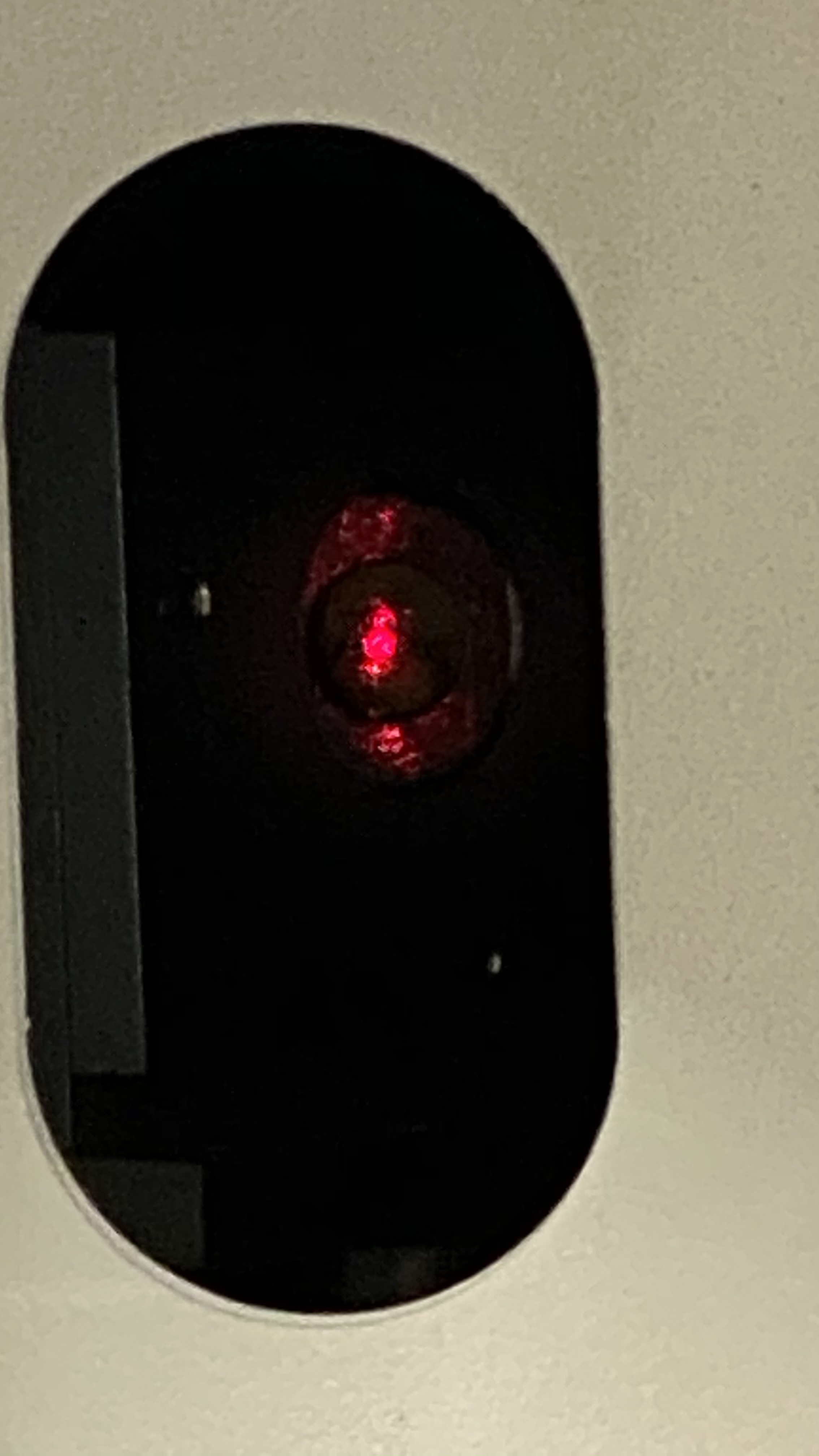
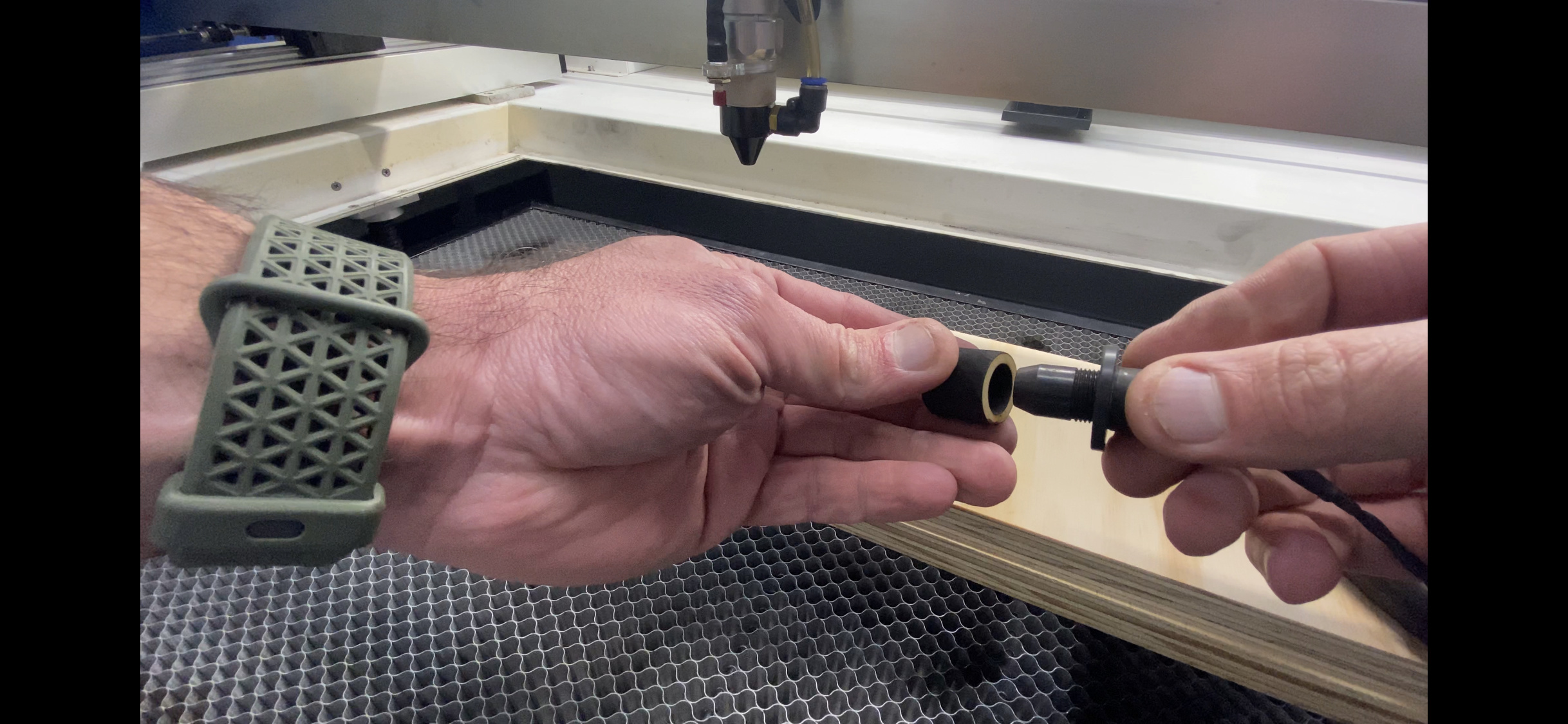
Red laser up through the lens holder in a snug adapter is the most amazing way. Someone had mentioned it on the forum a few weeks ago.

I’m going to fog the room with a fog machine because as @Dave01 mentions, PARALLEL is so critical. And understand it is parallel in all directions.

Why parallel is so important is because when x or y is jogged and the distance between the corresponding mirrors changes, being out of parallel means the overall end point of the beam is moving (left, right, up, or down).

Try this: point a narrow beam flash light at a wall as straight as you can. Walk toward the wall. The height of where the light beam hits the wall should be the same.

Now go back and point the flash light at the wall at an angle to where the light is toward the top of the wall. Hold the light at that same angle consistently in your hand. Don’t move the flashlight. (Don’t think about where the flashlight is pointed, think about the angle of the instrument in your hand only). Now walk toward the wall…

What happens? Well the light becomes lower on the wall as you walk closer. Walk backward holding the angle and the light climbs the wall.

So why the fog machine? Well, I already made massive improvements realigning with the reverse red laser up through the lens holder.

I want to try a method of the same but with pointing mirror 2 directly at 3 until I get perfect, single beam observed through the fog.

Then turn mirror two to reflect to mirror one and align 1 until a single beam forms.

2 Likes

In the third to last photo, it shows the burn in the center of the mirror opening. I understood that having the burn in that location is not going to provide for a beam path to the center of the lens and nozzle. The reverse red laser method should bear this out. Can you confirm this?

Depends on the #3 head. Some are spot on, others are not. Too many assume that the incoming hole to the #3 head is lined up wit the center of the mirror. Sadly not all engineers think that is important.

It is another factor in getting the larger mirror and lens size head. The lager mirror to compensate for a possible offset in the mirror to incoming hole to avoid beam clipping, and the larger lens to get the M22 nozzle thread for easy focal length changes.

I suppose that means Leader Jeff got one of the well engineered models!

Looks like he did. Many do hit the mirror center very close to the center of the entrance hole, but it is not a sure thing. I believe Russ hits the center of his gold head a little high, and I hit my black one 2.5mm high. I’m right on the edge of beam clipping. It’s was one of the deciding factors in switching from the stock head to his MK2 lightweight aluminum head. The mirror is fully exposed, no chance of beam clipping. Add in the ease of lens tube / focal length changes it became a no brainier.

Hey Stroonzo,

thank you for sharing your way of calibration. I’m curious about the sensor on your head, what is it? I have seen this on several machines and assumed it is some kind of capacity/inductive/IR sensor for referencing Z but I don’t get how this could safely detect all materials at the exact same distance to the sensor and have never seen such a sensor to buy as an upgrade. So, what is it and how does it work? :thinking:

Cheers,
Brian :beers:

To clarify, just as @Dave01 mentions, I too was hitting mirror 3 slightly high prior to my last 3 hour alignment overhaul that included painstaking height adjustments on every point upstream of the lens holder.

I was having beam clipping in my furthest extensions of x and y, but this wasn’t necessarily because of where I was hitting my mirrors. The clipping was a result of never spending the 2 to 3 hours to truly do an alignment of the optics in the year I have owned this new machine and not being parallel.

The point is true: the larger the mirrors, the better. Hitting center isn’t important. But, consider that the raw / unfocused beam width exiting the laser tube is maybe about ¼" (6.3mm). This means you need to be hitting a 25 MM mirror as such (anywhere on or interior to the light green ring shown in this horrible graphic of a lens holder and lens): :slight_smile:

(single pulsed unfocused laser beam illustrating the beam width):

See how my old molybdenum (Mo) mirror was affected by the high clipping where the edge of my beam on mirror 3 was heating up the housing of the mirror holder.

And Shhhh… don’t tell anyone. I started to use my stock pile of Si mirrors on this machine. Yeah, they’ll be short lived with all of the 90% power layers on my W6 tube. But I have about a dozen of these.

I have a stack of polished copper mirrors coming.

@BrianF84,

Man, I hope I am seeing those push button switch pics wrong. Is that a block to space your work away from the nozzle for your 4" lens?

This may help:

Different blocks for different focal lengths / lens positions. I am going to switch to a universal focus block. Within Ruida’s auto focus settings, I can define the focus offset specific to the lens / lens holder I have installed. With this, subsequent to the switch closing, the offset adjusts from there.

Okay, I guess that work. I’ve never used the auto focus, just a step gauge between the nozzle tip and the work. My material rarely changes in thickness more than 2mm, so it’s easy to bump the bed up or down a tad… or loosen the lens tube and let it drop to the notch. I keep between 5mm to 8mm between work and tip for maximum air assist.

Took me over a month to explain to a guy on a different forum why him popping a 4" lens into his 1.5" holder and lowering his bed was not getting him the same results a friends 4" set in the tube properly was. He had his air assist cranked as far up as he could and drilled out the nozzle tip to keep it from overheating and still didn’t understand why he had problems. He al but accused me a faking my pics on my Google Mod Page at the end showing I had engraved and cut 1x6 clear pine with my 80W and a 4" lens.

How do i post a picture?

You use this.

thanks rick
i will try

0
Hope you guys see the pic.
Hope ya’ll under stand the pic.
This is hitting my third mirror.

No on the understanding.