Hi, everyone. I apologize in advance if this is a basic question but I’m still new to the software and have been having a consistent and very frustrating experience.
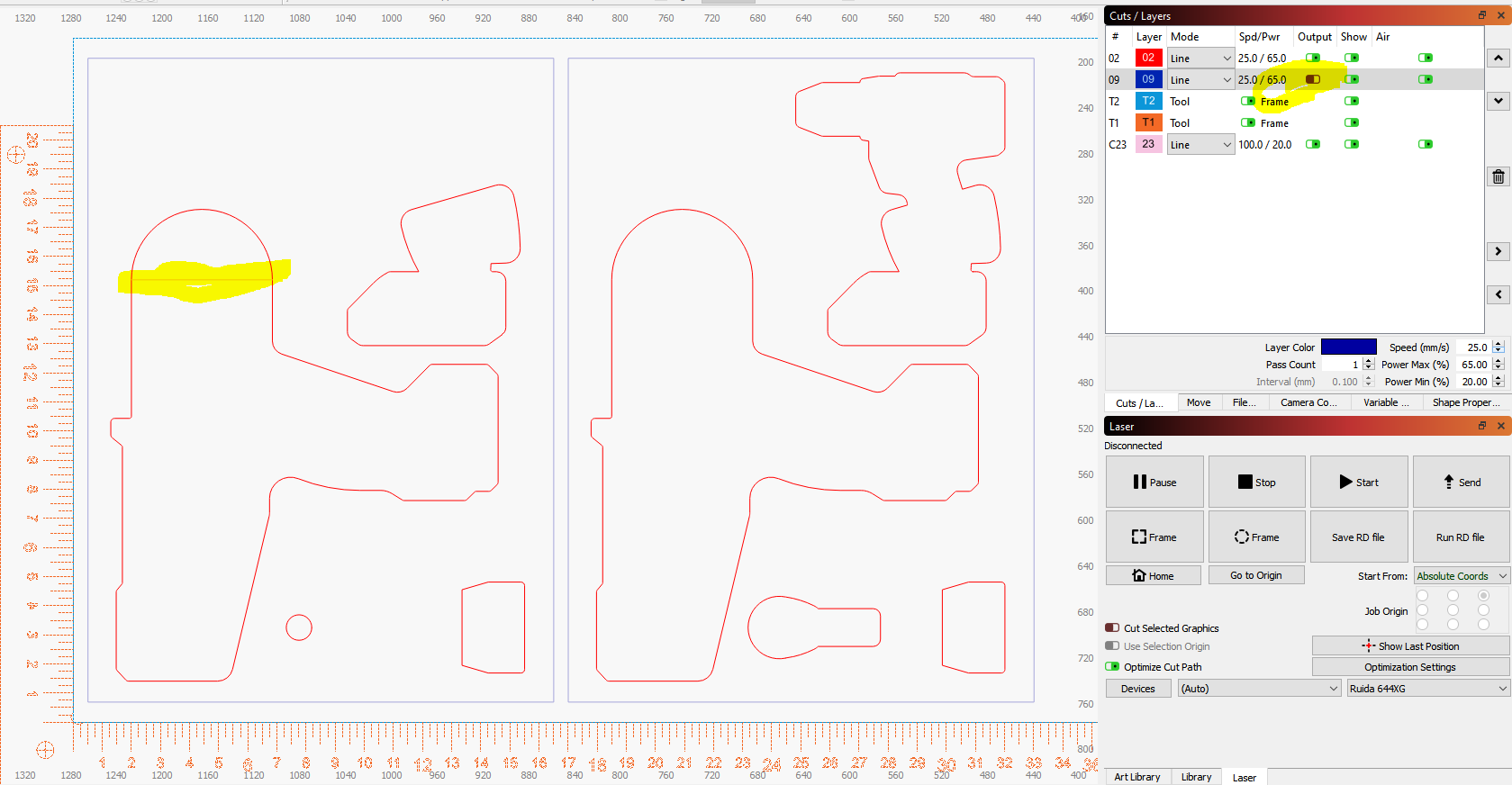
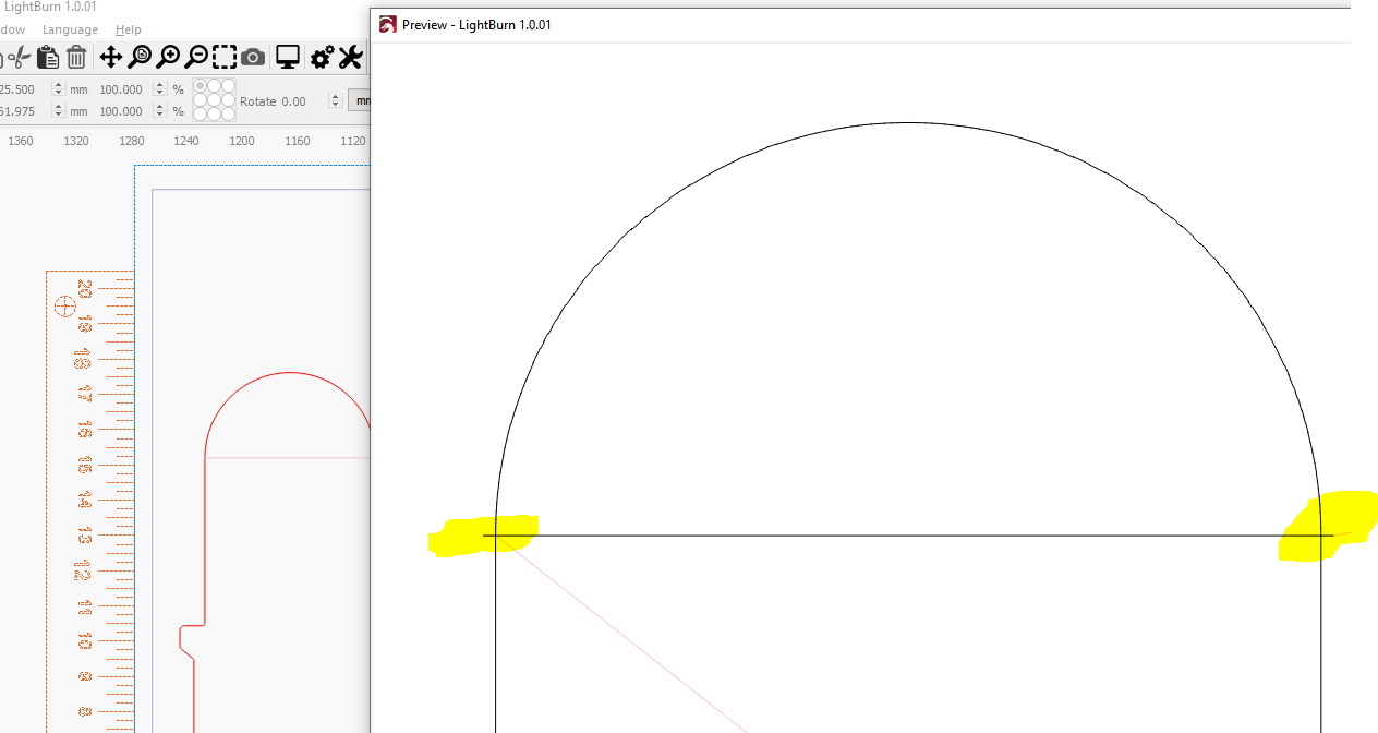
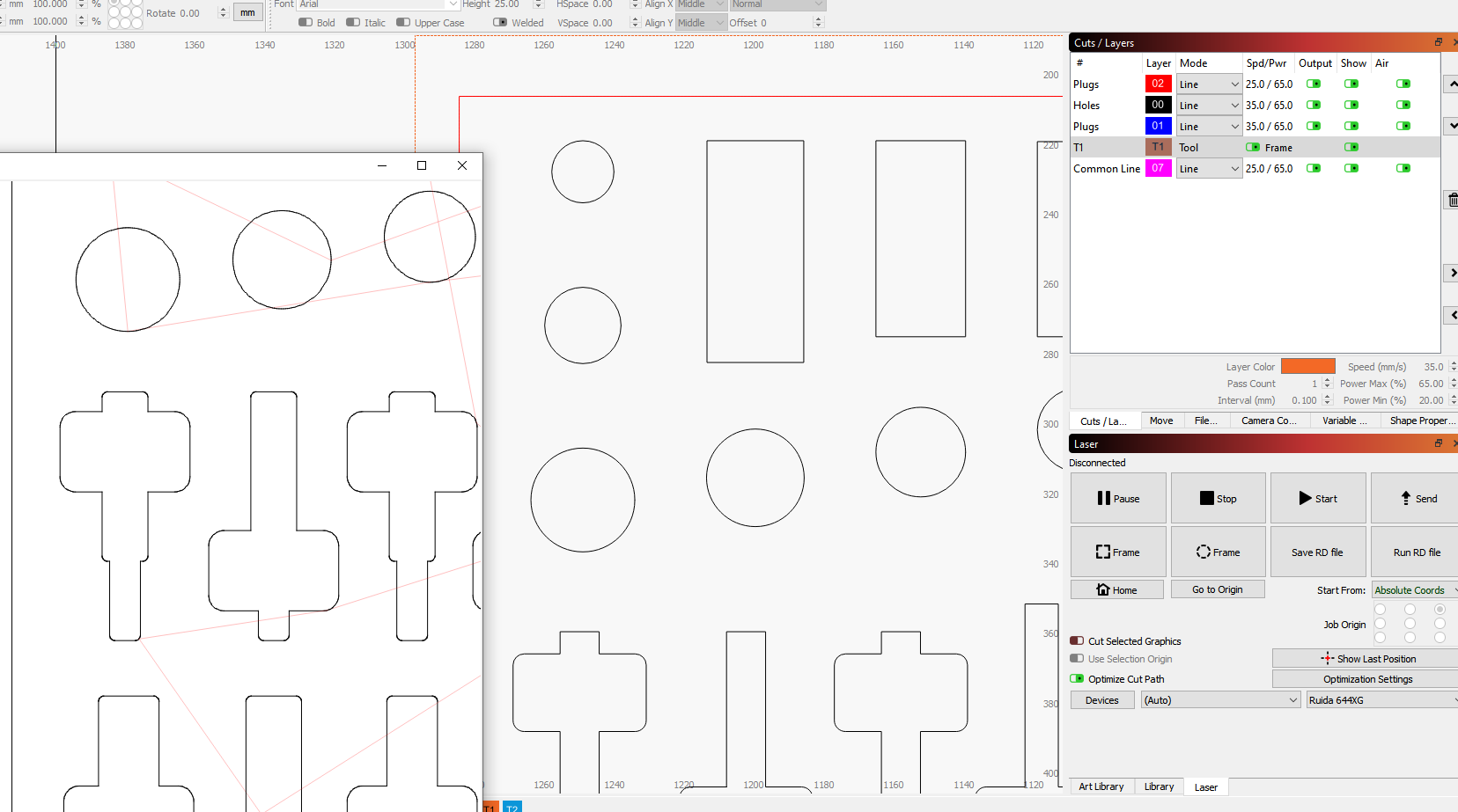
I’m cutting foam for tool box shadowboards and have a -1.75mm Offset for the interior geometries to account for an overall kerf of 3.5mm. If I have a border set to output and run the program the interior geometries’ kerfs go to the outside instead of staying in. I’ve drawn a single horizontal line from geometric quadrant to quadrant for reference. You can see here that with the outer border not set to output, the tool path offsets in, as desired:
This is forcing me to output two separate files: one to cut all interior shapes, and then another to cut out the entire rectangle that they live in. Any input would be greatly appreciated. Thanks in advance!
I believe it’s working correctly. If you are cutting a part that is not the target, such as a hole or the foam for a tool, you want the tool path to be inside or smaller than the outline.
Kerf is the width of the tool cut. If you draw a 5mm circle for an object to fit into. The finished hole needs to be 5 mm in diameter and the laser is 1mm in diameter or kerf. Chose inside kerf (negative number) of 1/2 the tool width since the other side of the tool cut is ‘inside’ and scrap.
This is a basic starting point. Probably will be too tight, since it will not have any clearance to fit together. but you get the idea…?
Materials not only change by batch, but in the SW desert a passing thunderstorm plays havoc with my cuts and engraving.
Thanks for the input, Jack. I’m pretty familiar with kerfs and feel fairly confident that I have them designated properly for the shapes to be cut.
To establish kerf I found the speed and power setting that achieved a thru-cut in a single pass as I was looking for. I drew two geometries, a 20mmx50mm rectangle and a 30mm diameter circle. I cut both geometries out on their respective lines. The 20x50 measured 23.5x53.5 and the 30mm circle measured 33.5mm in diameter. That indicated a 3.5mm total kerf, so an offset of plus or minus 1.75mm depending on if the geometry is an interior cutout or an exterior.
I cut both shapes again with a -1.75mm offset and was left with two holes in my material that measured 20x50 and 30mm; right on the money. To cut plugs for these holes I made my offset a +1.75mm and was given a rectangular solid that measured 20x50 and a cylinder that measured 30mm in diameter. All checked out there.
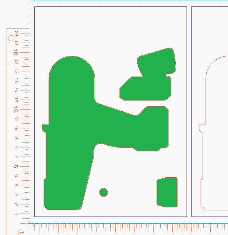
The area highlighted in green is what I want removed.
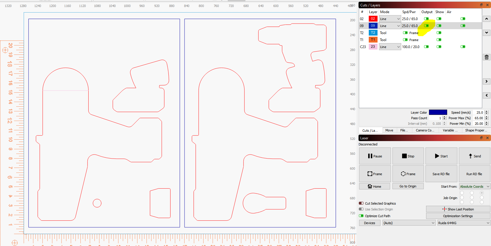
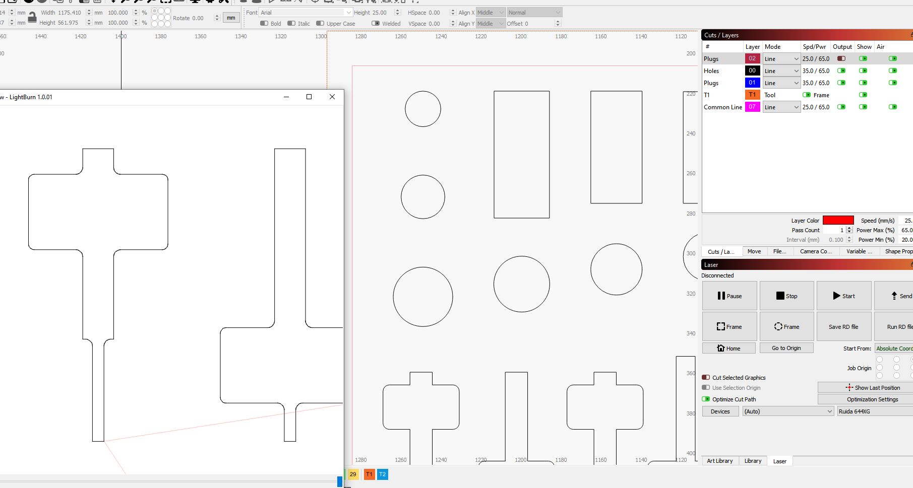
The layer these shapes are drawn on have been given a -1.75mm offset. When the blue border is supressed so that it does not output, then the offset goes to the interior of these geometries as desired. BUT, if I select the blue border layer to be output, then the centerline of the tool path offsets to the OUTSIDE of these geometries. I hope that helps. Sorry if my original post was unclear.
Somethings not right there. Turning a layer on or off shouldn’t have any effect on the kerf for a different layer.
Hopefully one of “the team” will come along and either confirm that’s a bug, or explain why it’s not.
Can you share the file or one that exhibits that problem? I can’t seem to replicate it here using simple shapes on 2 layers.
Most of the time with this group, if you can, post the offending file(s.) Some file, like .lbrn and .lbrn2 along with .png/.jpg can be dropped on the reply or edit window and they will be uploaded. Other file types or large file need to be in something like google drive and just supply us with a link.
I tried to duplicate it with this file. I assume the blue layer is not the T2 layer.
In the preview it does the reference circle, then the + offset, - offset and the ‘blue’ layer.
I believe LB is working as designed in the case you describe as the original problem. See this post for an explanation and how you can cut as you desire with correct-side kerf offset with just one file or run.
Thanks to everyone for jumping in to help out here. I really appreciate the support. I’ve had this same issue appear pretty consistently on several files over the last week or so. I’ve attached a few for reference.
In the attached file (Milwaukee 12T Bottom Drawer.lbrn2 (103.5 KB)) the problem will appear when layer 09 is toggled on or off for output.
In the attached file (20mm.lbrn2 (104.9 KB)), the problem will appear when layer 02 ic toggled on or off for output.
I had wondered if there were issues being created due to a few of the geometries being smaller than 3.5mm in width and therefore creating trouble when the offset made overlapping tool paths. I made separate programs that eliminated these suspect geometries and/or used common line cutting as a work around, but the problem has continued.
Heaven knows that 90% of car problems happen between the driver’s seat and the steering wheel. I’m hoping (and expecting) that it’s a simple user error here.
Well, I opened the “milwaukee” file and I’m seeing the same thing as you with the offset changing depending on whether the outer shape/layer is turned on or off.
If all the shapes were on the same layer i would expect that, but with shapes on a different layer I would not.
However, it seems to be a known thing and whether it’s a feature or flaw is apparently in the eye of the beholder.
The link Lou posted talks about it and it has to do with “Order by Layer” being set.
If you haven’t read Lou’s link above then you should.
I think it was alluded to that the kerf function operated on a layer system and that’s how it knows inside from out. I’m sure the developers will jump in and correct us about the workings, but I’d bet, as Hank stated, it’s a known operation, pro or con
If you enable ‘Order by Layer’ in the Optimization Settings, it only looks at the other shapes on the current layer to decide whether a shape is inside or outside, so enabling that will make it consistent.
With ‘Order by Layer’ off, it’s looking at the entire content of the file to decide the order, and when you disable part of the file, that order flips. We could pass the entire file through the inside / outside sort, and exclude them from output after that, but that’ll take some rework.
Lou and Oz,
Thanks for pointing me toward the ‘Order by Layer’ solution. I understand and respect the logic here from a development side and will just have to keep this on my own QAQC checklist as I work with the software. Thanks again for the very quick support here!
Mark