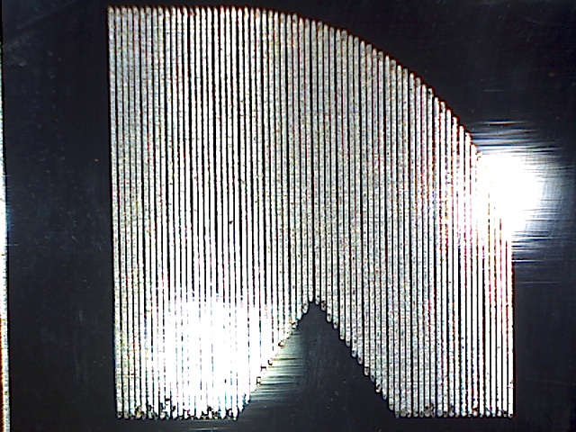
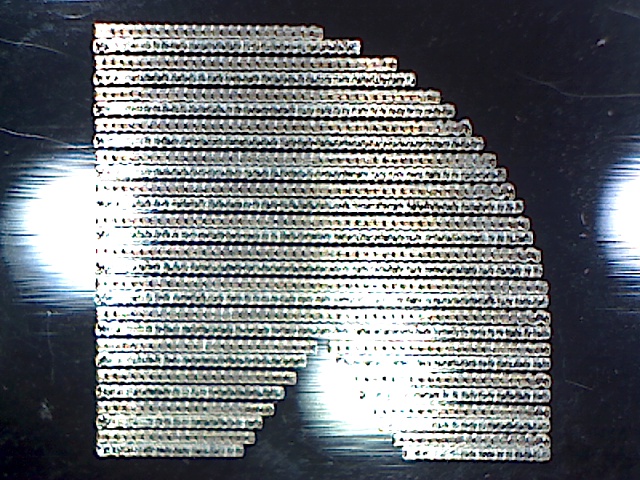
If you zoom in and look closely at the vertical interval output, you can clearly see that vertically (i.e. in the X direction) a laser focal point width of less than 0.15mm is being achieved
However, when looking at the horizontal interval, the output is very disappointing. It is only when looking at the 0.35mm and 0.4mm intervals that the horizontal lines can be clearly identified and/or separated
From thee tests, it is clear that the best focused dot size my A40640 can achieve is approximately 0.13mm x 0.25mm AND IS MOST DEFINITELY NOT A SQAURE DOT
Is this typical of the A40640 laser module? Does anybody else have this experience? Do I have a faulty unit, that isn’t meeting its stated specification?
Not sure how typical this is for that module. One thing to check is that the laser module is square to the work material and that it’s not cutting at an angle.
Did you also do a focus check on the horizonal line?
from your images i can see that you have a mechanical problem in you X axis. I see a lot of wobbling. You can clearly see it in your first image, just for example look at the “S” of Scale.
Is not a dot problem of the laser module itself.
Can you share the test in your first image so i can try with my Neje A40630?
. . . I also burned a single dot using the “FIRE LASER” button and took a close up image of that with my microscope, which also showed a rectangular dot
and this is not right, my A40630 has a square dot, yours has two separate diode and their beams are aligned by a lens inside the module, so if you have a rectangula dot maybe is damaged and it will be better if you contact direcly Neje showing them a photo with the rectangular spot.
if you look at the first image in the second row you can see that they talks about a square spot.
Btw thank you for the attached test
. . . and this is the Lightburn file for the kerf test. You just need to push all the individual squares “UP” & “LEFT” to the XY0 corner, then measure the total gap created and divide by 10 to get the kerf size for the material used (2mm birch ply in this case). A40640 Kerf Calibration (0.1mm X & 0.2mm Y).lbrn2 (2.5 MB)
The lens on the Neje A40640 can be turned [to increase its distance from the diode], as described on the Neje Wiki, to adjust the laser dot to be in focus at distances of between 55mm and 33mm below the lens . . . a shorter focal distance will generate a smaller “dot” and a reduced depth of field [i.e. distance that the ‘dot’ remains in focus] when compared to a longer focal distance
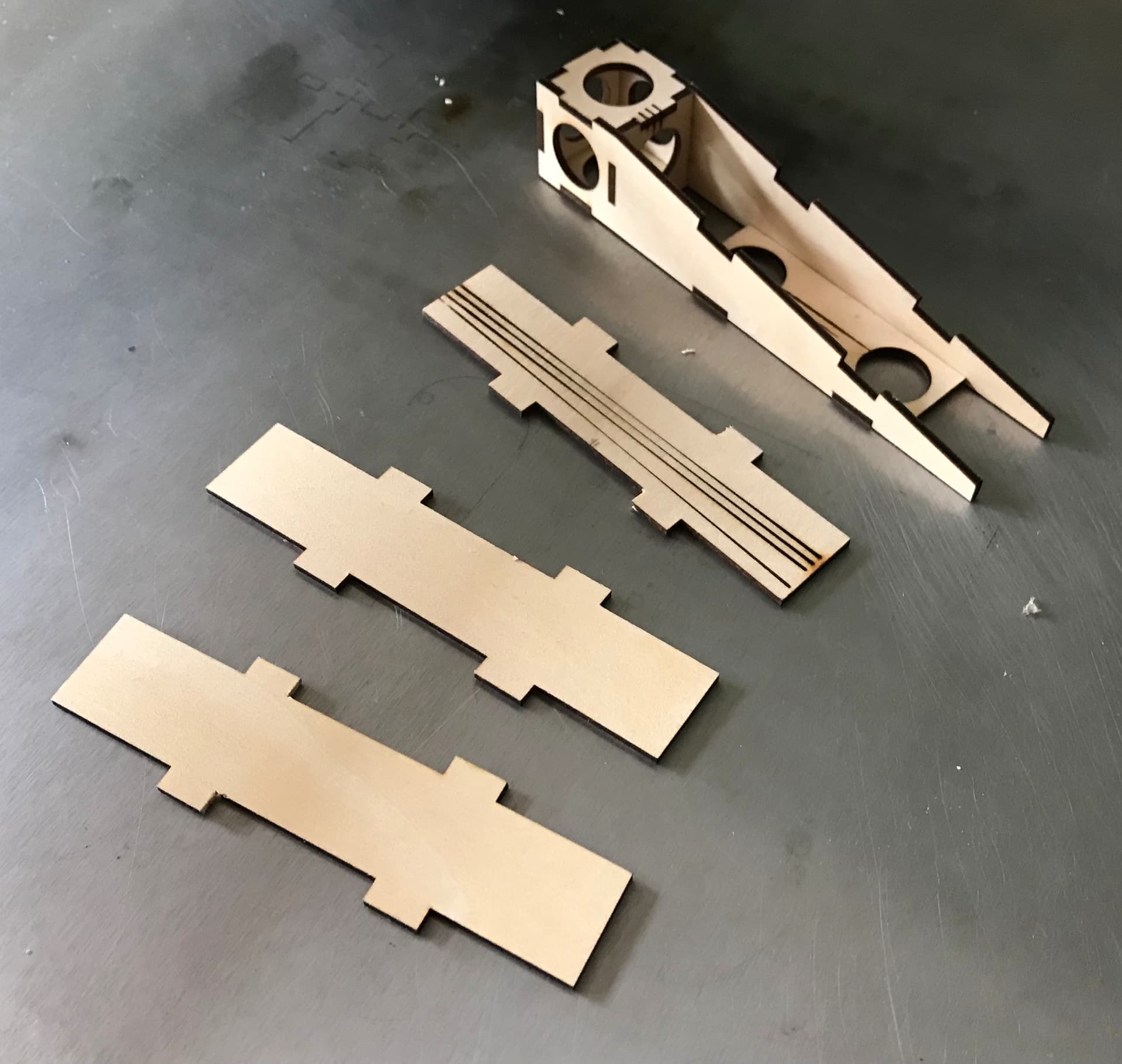
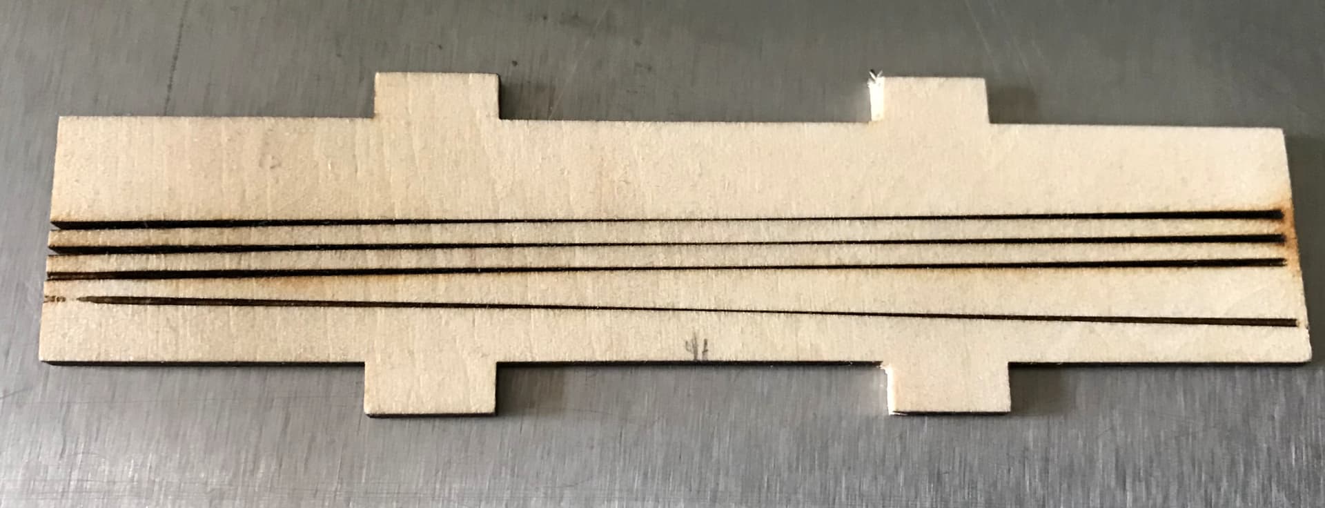
. . . I first lower the A40640 so that it is resting on the top of the jig [this sets the height to the laser module heat sink to precisely 25mm]. I then position it to engrave & cut 100mm lines in both the X & Y directions [as can be seen on the first of the three test pieces in the picture above].
Given the 25mm to 5mm height range of the test piece when placed on the jig, it can be clearly seen in the above image that the laser travels from significantly out of focus through perfect focus and finally to significantly out of focus again.
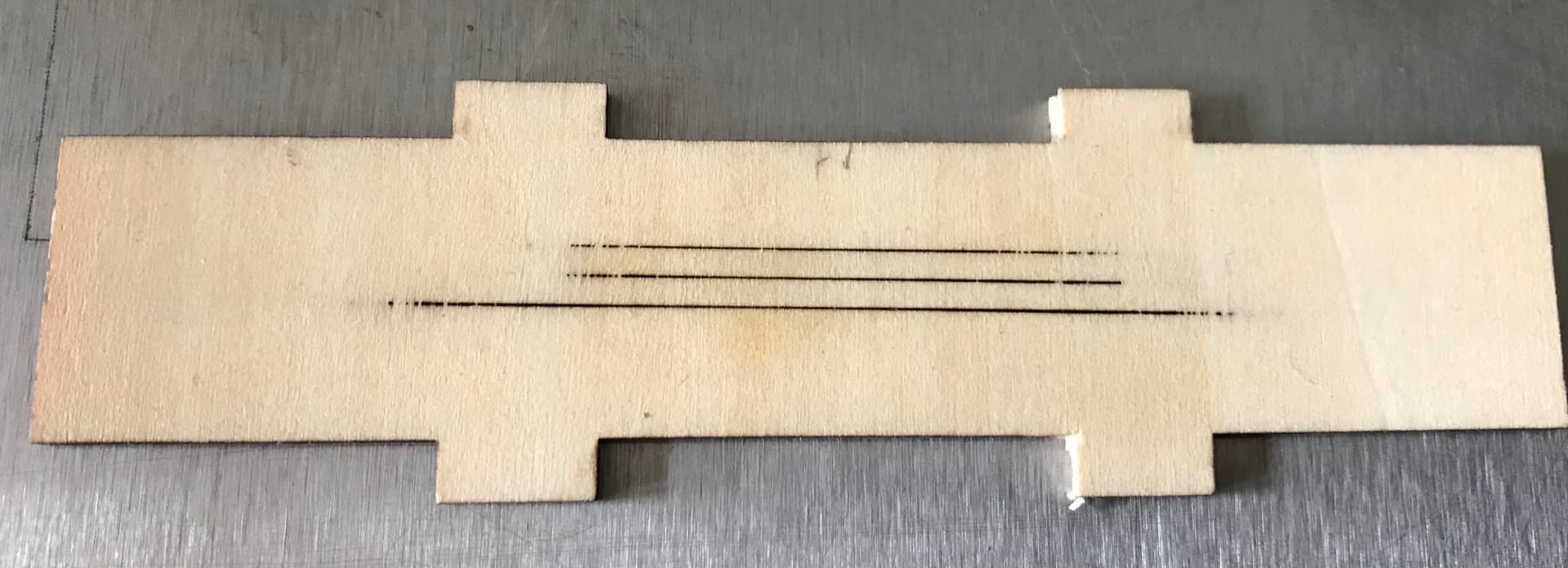
I don’t rely on simply visually trying to work out where the line is thinnest [as seen in the first of the above two pictures], but I look at the reverse to establish the start & mid & end point where the laser successfully penetrates through the material.
Having noted the start, mid and end points I then place the test piece back on the jig and measure the height from the base to each of these three points using digital calipers. Subtracting these three numbers from the 25mm starting height of the laser then gives me the optimum focus distance [the mid point] together with a “depth of field” [the start point minus the end point] in which the laser is sufficiently focused to still cut through the material.
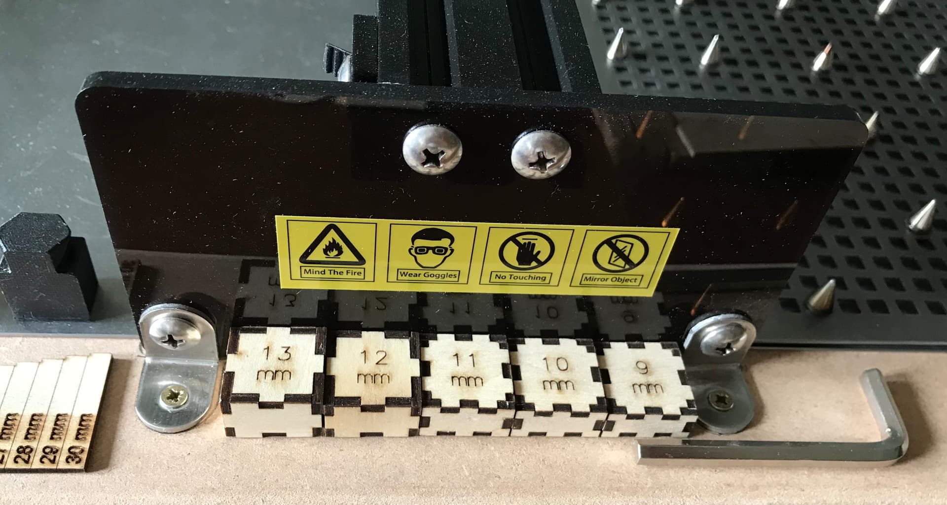
From then on I have a set of blocks that I can use to quickly and easily focus the laser on the surface [or at a given depth into or above] whatever material I am then working with.
Did you check that the laser is square to the material? If so, then likely that this is either a manufacturing issue or within expected variation. It’s fairly common to have an asymmetric dot, especially with multi-diode lasers.
Also, not sure how focal point can be expected to be square when the laser module itself states an asymmetric focus (0.04x0.06mm). Something doesn’t quite add up.
I have raised this issue with Neje [on their Forum] and so far they haven’t resolved or really addressed the issue.
What they did, two days ago, was to “unlist” the topic from their forum . . . one might presume that this could be because they already know about the issue and that the Neje web site therefore misrepresents the performance and/or specification of the A40640 Laser Module . . . on a Discourse Meta based forum “unlisting ” makes the topic private, which prevents it being visible to other forum users and stops search engines like Google finding the topic !
When I asked Neje why they “unlisted ” the topic, they said that they “Hide posts to protect user privacy, please understand ”
My response [on the forum] “Please remove the “unlisted” status of this topic . . . I am the user, I do not want my privacy protected, I want to obtain the input and experience of other forum users to help me solve this problem [that is why I posted this issue on the “forum”]”
@ berainlb . . . not a single thing, the topic on the Neje Forum contains the same, but less information than is posted in this topic on the LightBurn forum.
No, Neje are not addressing my concerns . . . the issue is that the Neje web site & wiki state the specification and performance of the A40640 . . . whilst, the product I have received simply doesn’t meet that specification. [the minimum size of the focused laser dot, that it appears possible to achieve, is over 2.3 times bigger than that specified and is rectangular rather than square].
i am Suspect as i am from “competition”, but i noticed some issues on our Ortur dual diode modules
Rarelly - but happens - a knock in transit might nudge 1 of the mirrors enough that you get a offset, The worse i seen on support was 1.5mm apart! ouch On X the diodes were aligned, on Y the 2 diodes were 1.5mm apart.
I made the user adjust the belts like 20 times before i realized whats was going on
However our 10W does NOT claim a square dot, is nearly impossible to achieve that.
What i would sugest is, compleatly defocus the module to see if you can notice the 2 dots apart, seems yours are barelly out of spec, that makes diagnostics very tough.