I would do this
IDentify on your board Ground (by continuity test - WITHOUT power connected granted)
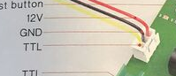
On the Laser connector
You cn test this by probng usb shield and the B pins on your connector on the motherboard
When it beeps you have ground
Then the other pin is TTLPWM (5v at 100% power should be normal) 3.4 with normal multimete mode
Then connect to A connectors of the Neje Board
Giving the laser its own power
so the laser will have its power, the board another
So you only need GRDN + TTL (PWM)
Alternativly, Ultimately you could connect your laser cable to the INPUT C → and then neje to the neje Laser module port for testing, but Dont go above 20% power on 1 single power adapter, unless is 5AMPs or more.
First, notice english is not my native language, so sometimes I lost critical information. Also, I am not a hardware guy, but a software one. I am very lost with cables and so on.
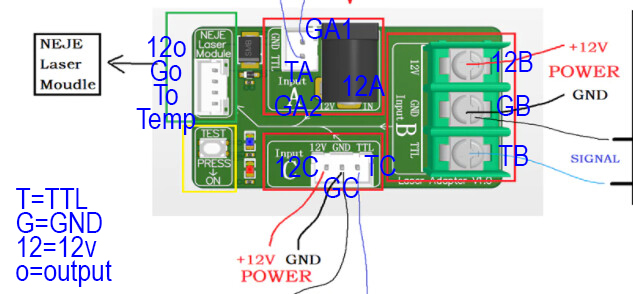
I have labelled all the pins in the MiniNeJe board.
0-Checked all the G (gnd) pins, and they are connected. (continuity)
1.- If there is power on the CNC controller and not in the NeJe board, the laser not even lights on.
2.- If there is power on the NeJe board and not in the CNC, the laser just fires at powerup at (i guess) full power.
SO, as test 1 & 2 shows, there have to be power on both “black” connectors.
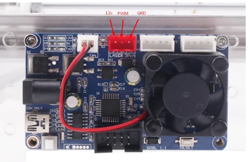
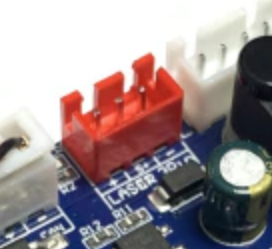
Currently, my CNC has a 3 pin connector (the red one) connected to the C connector on the NeJe board. I think it is as it should.
BlockquoteHowever i would use GRD and TTL only (Input A) which might require modifying your cable by removing the 12v pin
If I understand correctly, I have to modify my 3 pin cable from CNC to NeJe board by removing the “12v” pin/cable and connecting the other 2 to the white A connector. AM I right?
Excuse my ignorance, but wouldn’t there be problems connecting 2 different GNDs (one would come from the black connector on the NejE board (GA2 according to my chart), and the other from the CNC through the new cable to the white A connector (GA1 according to my chart). I repeat, excuse my ignorance in these electrical issues.
This is what i would do yes that is correct
The ground will alwys be common between electronics, as they are shared across
What you dont necessarely want is 2 different power inputs
Ultimately it would work but is easier to isolate them
However you could JUST connect your cable from the CNC to the Input C not put your 12v into the black connector and try running the laser at low power as i dont know the rating of your power adapter
Then some polarity seems off. need to get that multimeter and double check everything
Also the data sheet of the board would help to know what exactly it outputs on theTTL/PWM pin
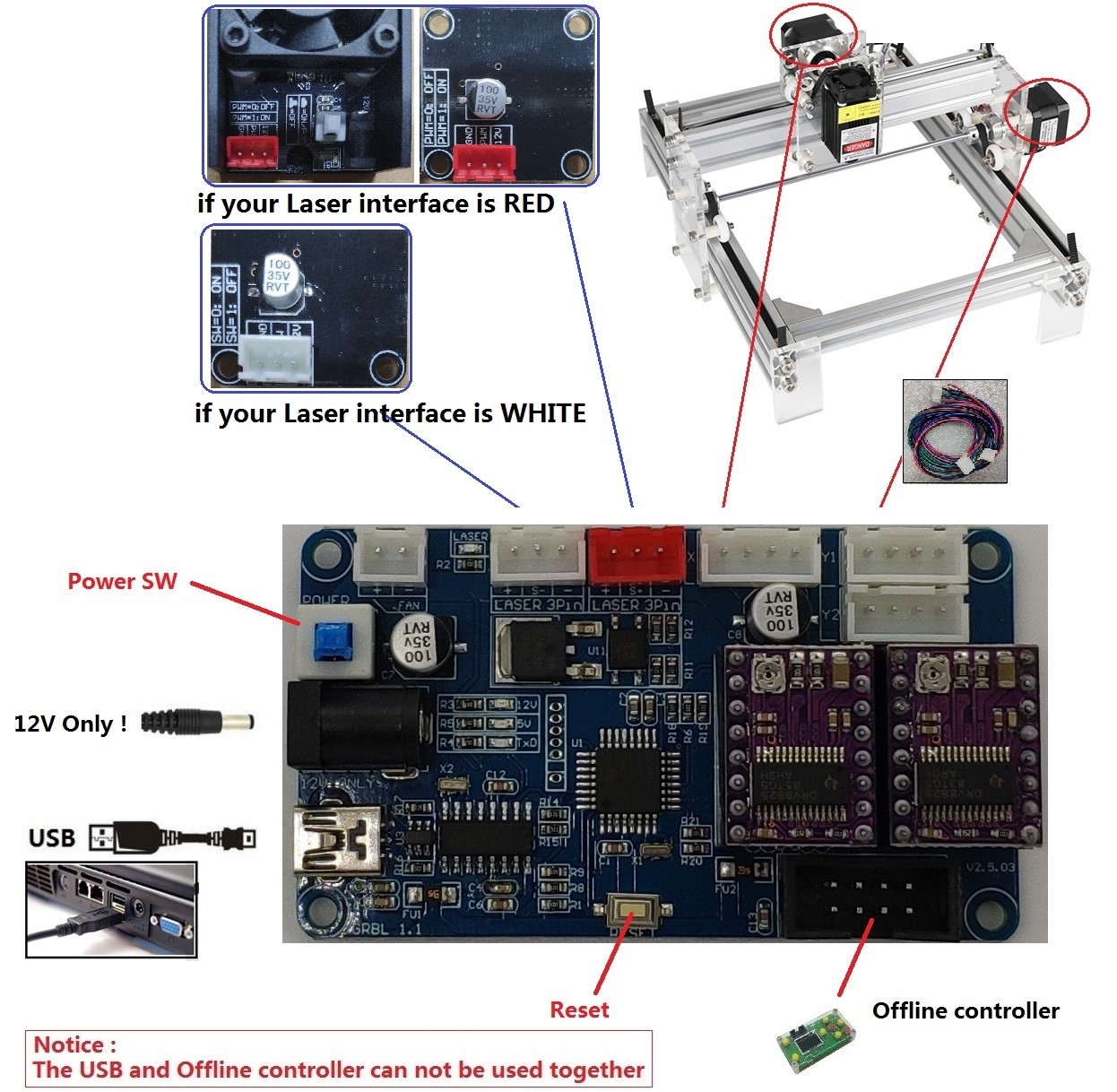
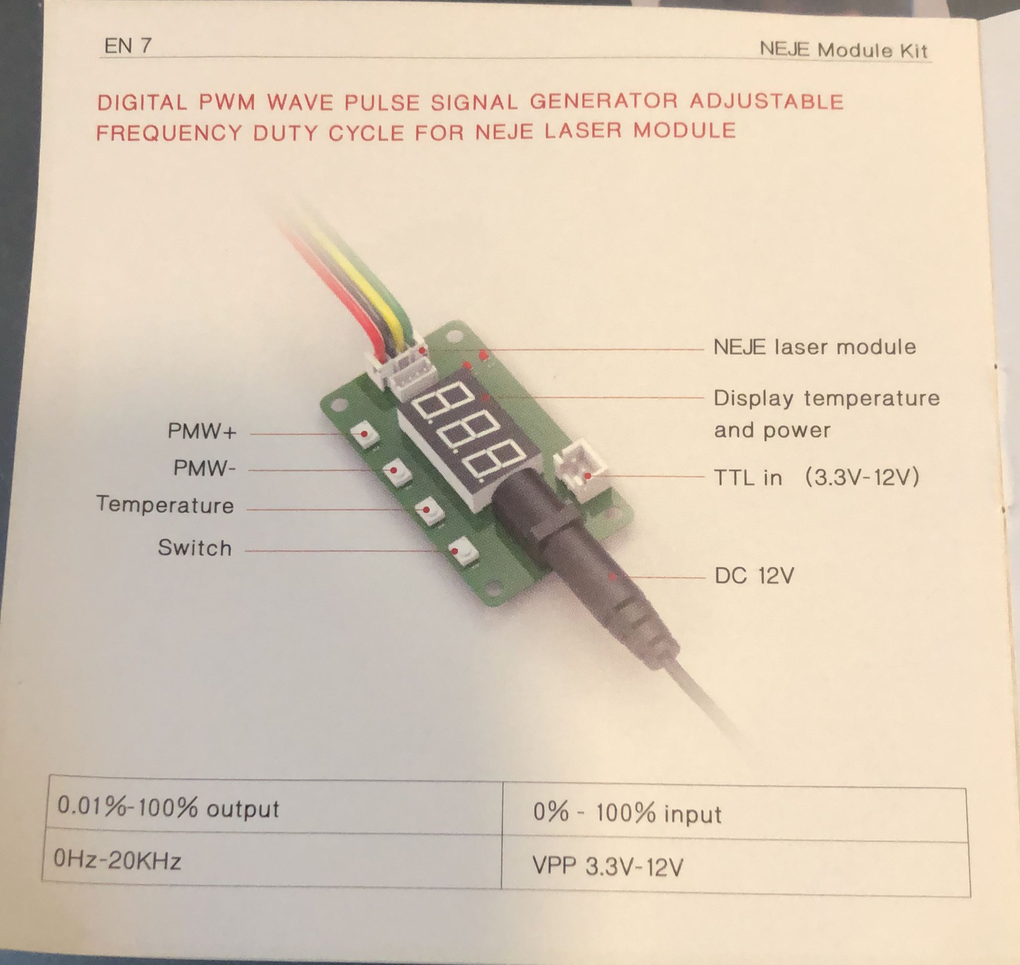
This is the one shown on the documentation. Notice the “dual” 3pins: for a laser interface red, and for a laser white interface. My controller has only one red interface. Question to myself: what is the difference?
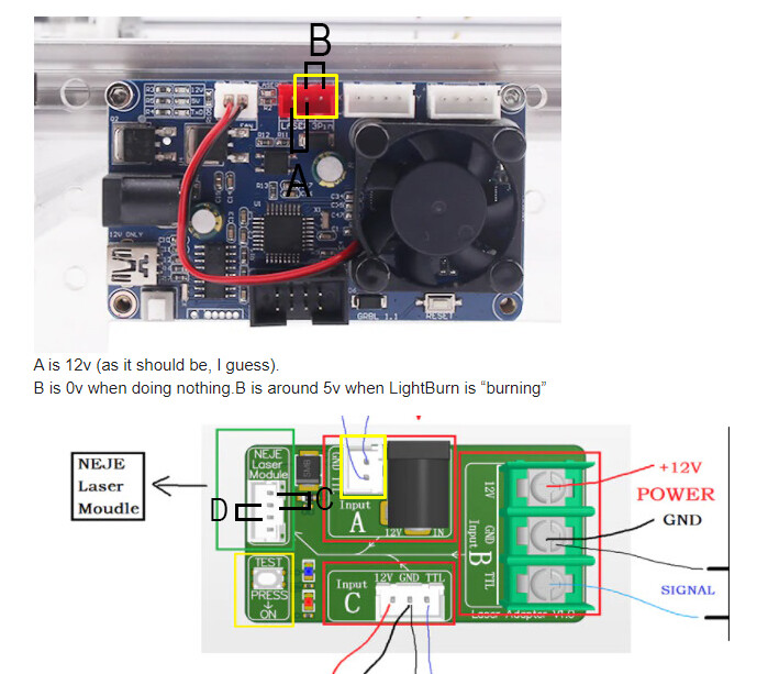
While measuring, the volts where -12v (not 12) but I did not give it “importance”; will double check later.
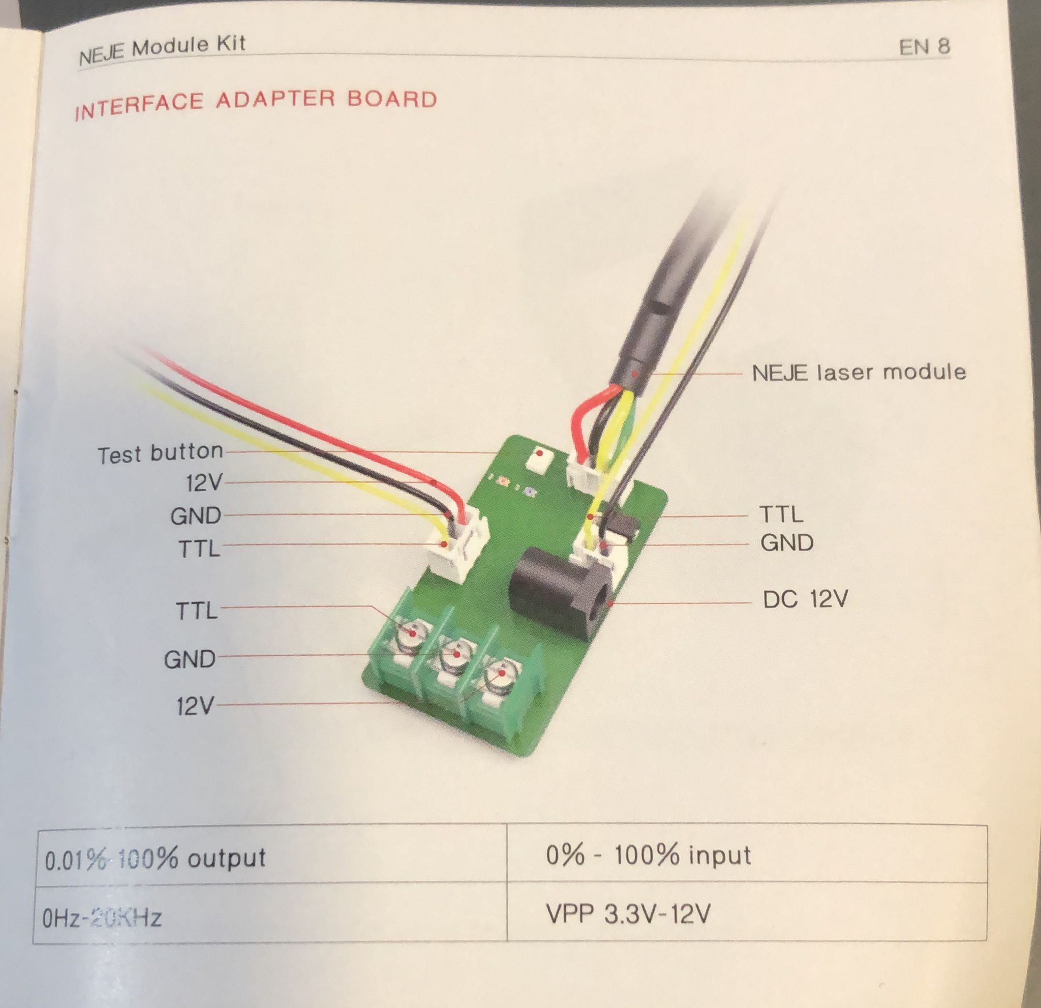
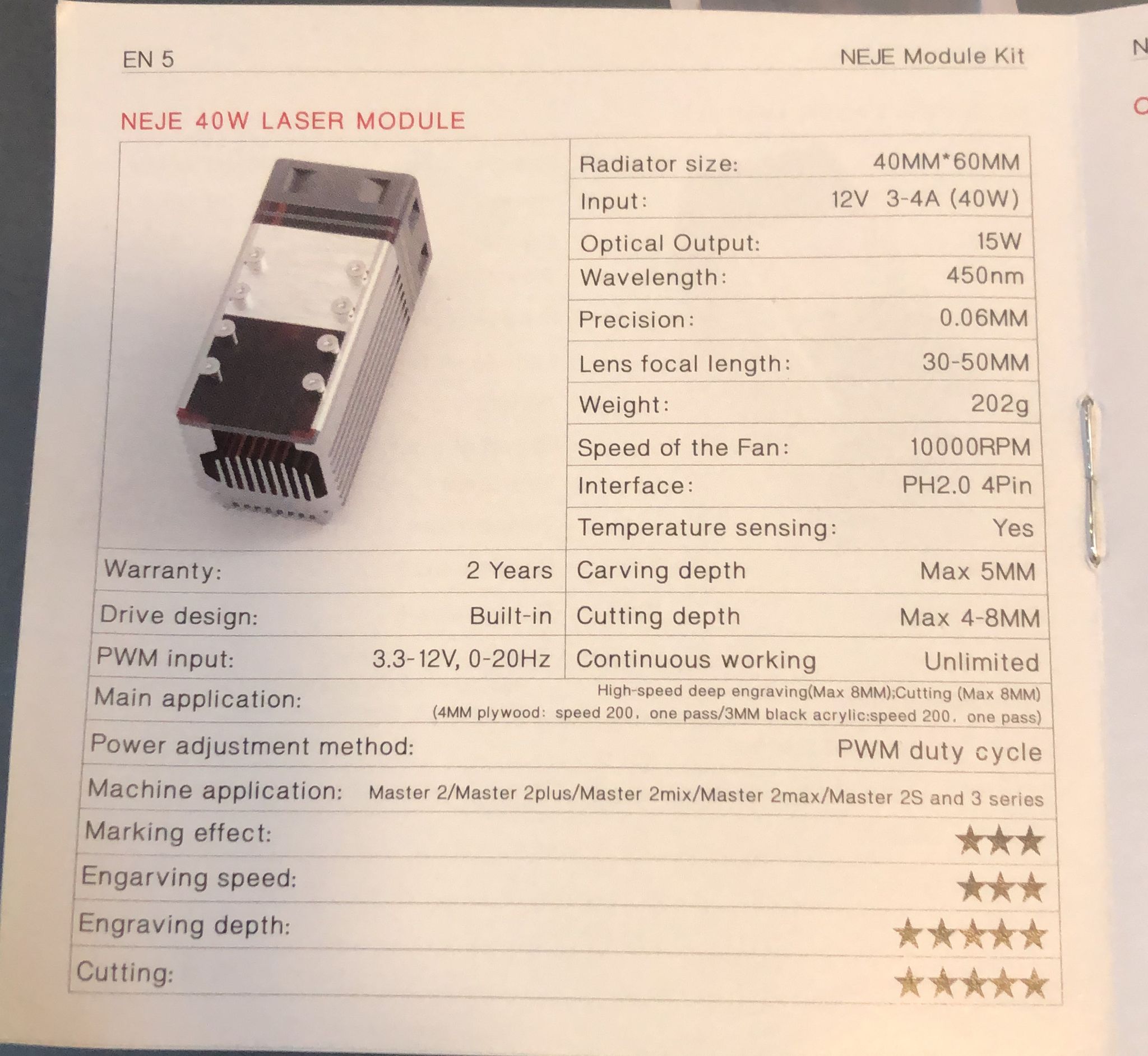
BTW, here you have the only documentation they sent me with the laser (I guess the laser on the paper is not even mine):
Easy test. Set the laser to engrave, test carefully the LEFT and right most pins. Left should be +12 right GRND
If so, then you know the right and center is PWM
In fact notice the laser head assembly shows the same pinout
Center PWM
Not very standard but not unusual
Once you identify the output correctly on the board, you can link it to the neje adapter quite easily
By matching
NEJE, NEJE, NEJE
Say neje 5 times it will stop working !!!
WORST NAME IN LASERS SOLD IN THE WORLD !!
OVERATED IN QUALITY ,
THEIR WARRANTY IS NONEXISTANT!!
BUY AMERICAN !! APERTURE LASERS ,
George will treat you right .
I’d like to see the diode in action if you can upload a video. Once mine dies I intend to buy a better and more powerful diode for portability as I have some contacts that want me to do stuff onsite.