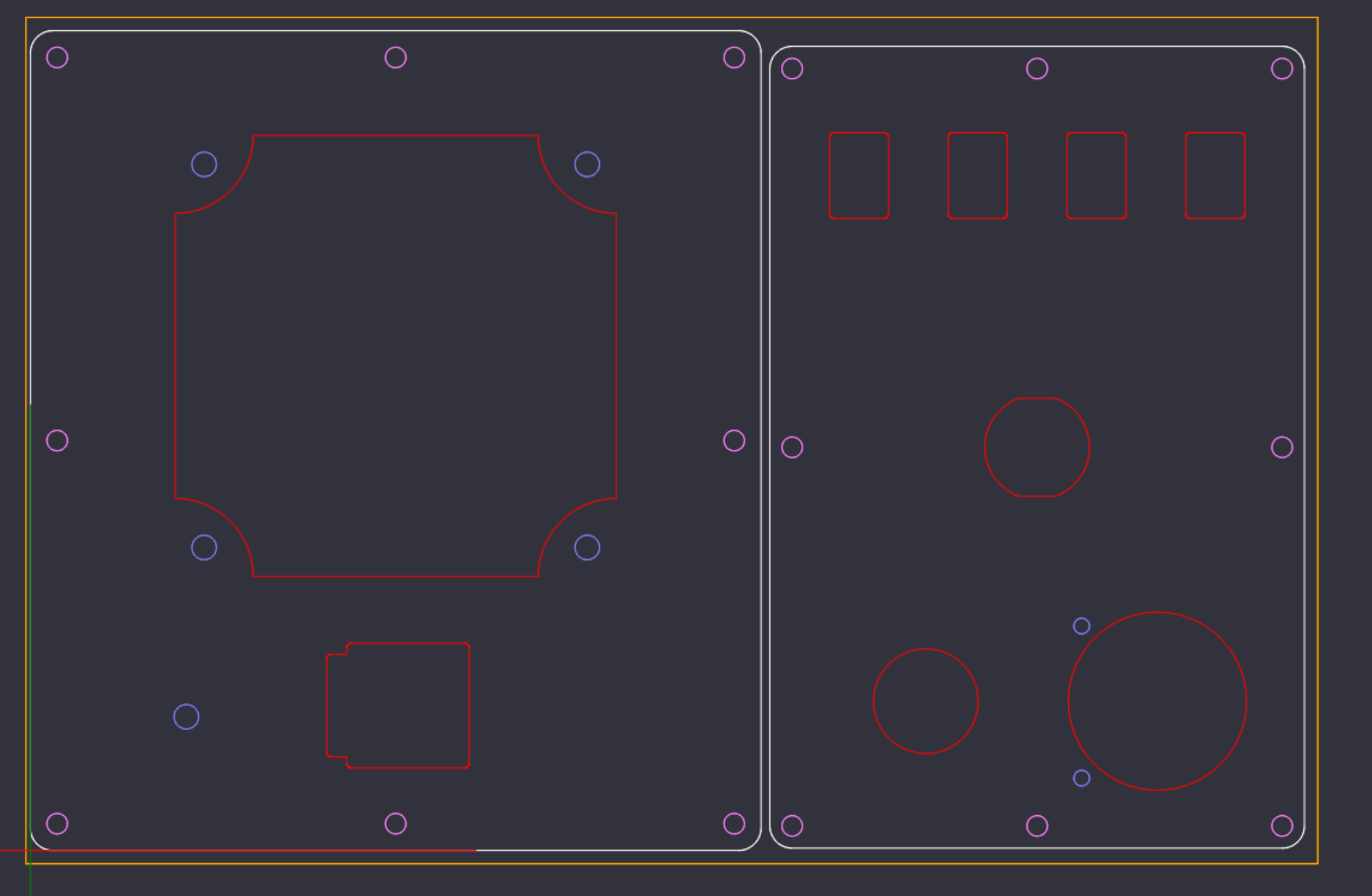
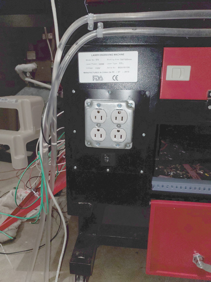
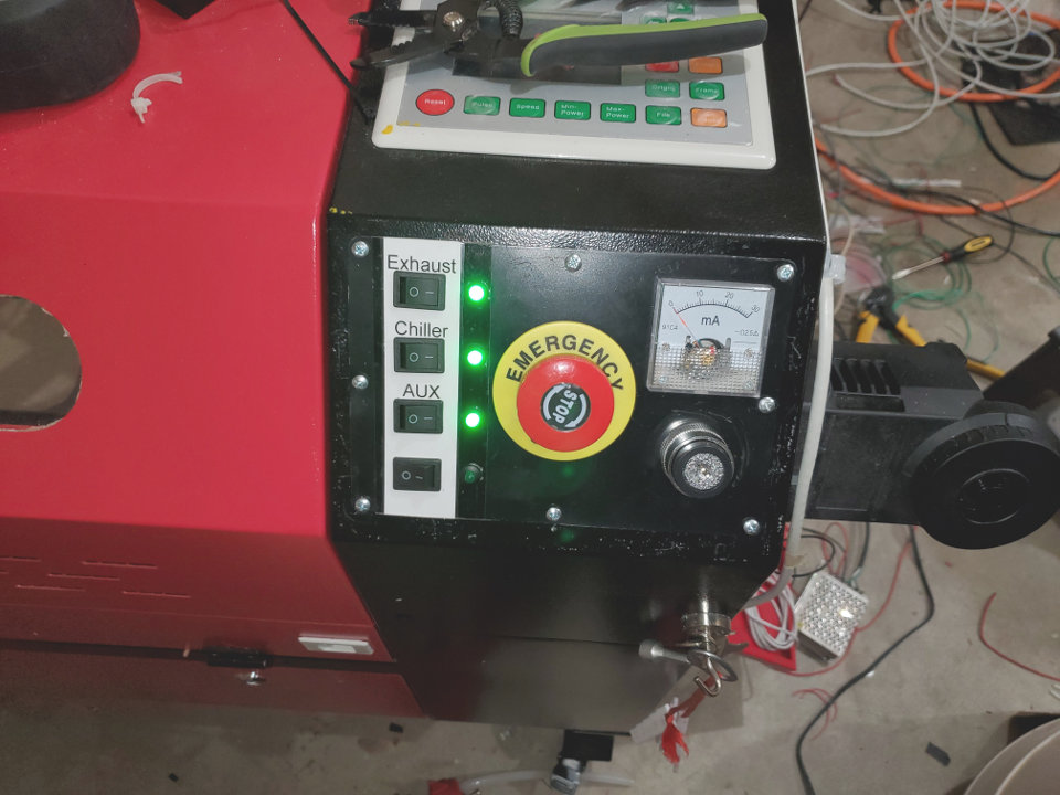
A bit of a teaser. I’m rebuilding the front panel and power distribution on my 700x500. I’ve been really unhappy with the “quality” of the rear outlets and wanted to move the power meter I added to make it more visible. I also wanted to add some control switches. The rear outlets will be switched via relay for blower/exhaust, “AUX1”, and “AUX2”, with one outlet always on (if the chassis is on). The 4th switch will be dead; maybe future rotary enable or something…
I used 22ga steel cut with my 6040 CNC. No plasma cutter for me. Learning a bit as I go along with the CNC too, though. The front panel is cut and I’m waiting for the paint to dry. I still need to cut the rear power panel. I’m using standard 15A duplex outlets with a steel 4-way mount. Also replacing the C14 power receptacle.
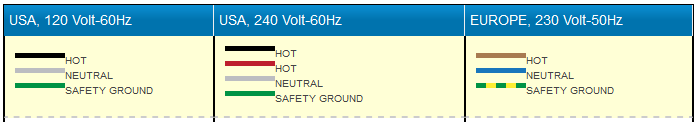
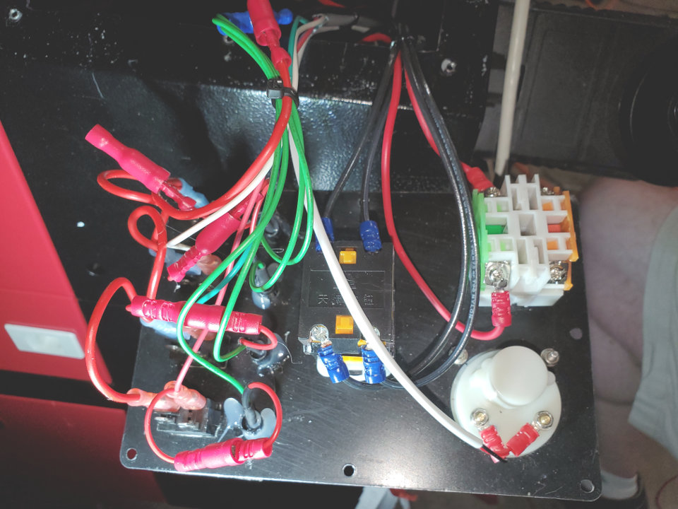
One additional point that make you go, “hmmm.” The neutral, in addition to the line, are switched which seems to be a bit of a bad thing. I’m going to re-do without a switched neutral. It’s also fused at 20A and I’ll drop that to 15A.
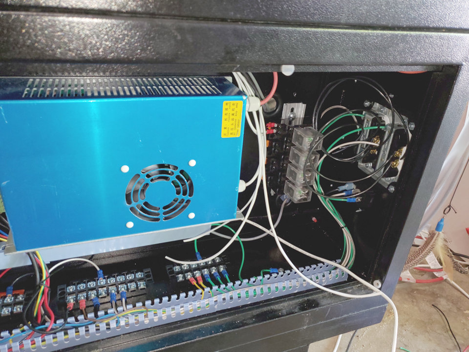
Most 220 to 110 conversions are done at the power plug and swapping the PSU’s. the switched second leg for them becomes a switched neutral for us. I took my incoming power and brought it into both side of the main. One side is for the laser, the other for my accessories.
Looks familiar. I swapped controllers so I had to build an extension on top for the display. Put all my stuff up there. Added a set of posts in series with the mA meter for a digital during power tests. It has a jumper between them during normal operations. Yes, I added LED’s for WP and Air Assist indicators along with the dual digital temp gauge. Contemplating a pressure gauge to monitor my air assist. I have three different pressure levels depending on the job.
My big reason for going up instead of on the angle was my stepper is on the right side for the X axis, and was very close to all the wires and such on the back side when all the way forward.
I’m planning on doing the same thing now that I see how it’s wired. One side of the E-Stop to feed the system/chassis and one to feed the outlets in back.
I took the outlets off the E-stop. If I had a problem I wanted to be able to kill the laser, but suck the fumes out. I also stole a power switch from an old power strip for my exhaust switch. It’s 15A, and a breaker to boot.
Now I do have a few switches on my angle besides the E-stop.I have my exhaust switch for the top half of the back outlet, and a switch for the lower half that my diaphragm air compressor is plugged into. Since I wired my neutral up direct, I took the laser power and brought it up to another power strip switch beside the E-stop. That makes everything on the angle 110V, and everything up by the controller low voltage. The diaphragm compressor isn’t used except for a back up. Putting the three pressure level air system together now,
I have some pics of the console mod on my Google mod page. You can see the angle switches in the pic of the last Cooling - DIY chiller pic. I have finished the table top on the mini fridge chiller since that pic. I’m torn between leaving the whole thing up on the long frame, or putting the laser back down by itself and being able to move the fridge chiller separately. The jury is still out on that one.
Hmm. Good thought on the exhaust on (off) the E-Stop. My first thought, though, would be killing the exhaust would reduce fresh air movement in case there was a fire.
What’s the use case for over-riding nozzle air, not under layer/DSP control?
With the Ruida controller, you can hold the pulse and travel arrow and make a manual cut to cut off materiel from a longer piece. In that case you want to turn the air on manually. The second wold be burn tests where you want air on your acrylic burn blocks. Usually you take an extra piece of tubing and extend the tube back to where you are doing the test. If it’s a programmed test, it will turn the air on via the controller. If you are pressing the pulse on the android app, you need to turn it on manually.
For me, the exhaust is on the main but not the E-stop. I kill almost everything with the e-stop but the exhaust. It pulls down and back away from everything else. If it does need to be killed I can hit the main switch. I’m also looking at the little fire extinguisher cans they hang in range hoods. One of them in the inside of the lid would be an automatic fire extinguisher.
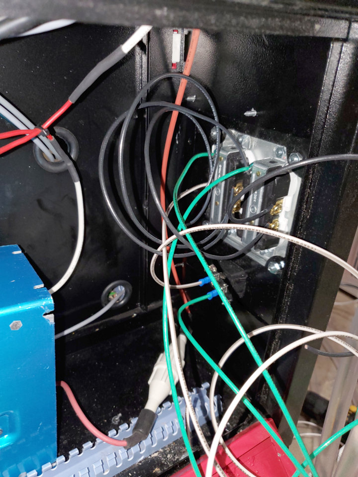
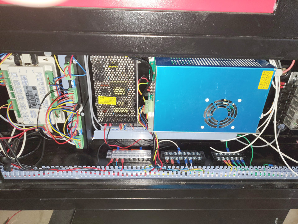
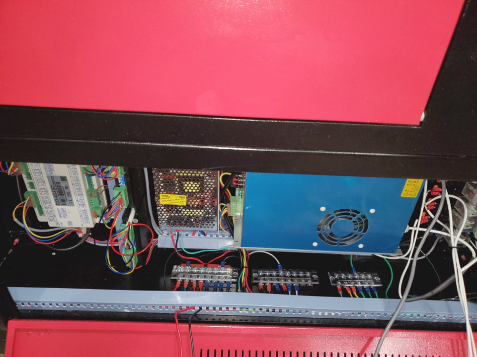
The work continues. Taking longer than I expected, but I found more that I didn’t like with the original wiring. Crimps were pretty bad quality as well. I ended up redoing all of the mains wiring. Ran out of wire to get to the outlets, and I still have the low voltage to do as well, but it’s getting there.
I’ll probably also put an acrylic shield over the outlets, but I have to get everything back together, first.
I hope to finish this up tomorrow. Some finishing work with wire management will have to wait due to a delayed shipment. I also had to replenish my stock of crimp conectors - twice! There’s a large number of wires, and they each have 2 ends.
On a more serious note, I can now strongly recommend that people take the time (with power unplugged!) to check the crimp quality on all connectors. I had two mains wires fall apart “just looking at them.” I’m using high quality connectors and crimping tool and the difference in quality is… extreme. I’m also re-routing the low-voltage connections to the panel through a different bulkhead hole in the chassis. The current setup is for mains and Ruida cabling going through the same hole. Some minor re-routing in the rest of the chassing for better separation of high/low voltage as well.
I’m going to end up with air pump (aquarium compressor), exhaust fan, chiller, and Aux outlets on the back. That will use up 3 of the 4 switch positions on the front panel. The fourth will go to… whatever in the future.
Based on what I’ve run into so far, I’ll also be replacing all the low-voltage wiring at some point in the future as well.
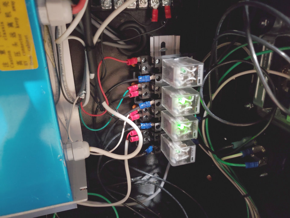
Almost done. Need to finish up the relays. My wire management (adhesive zip-tie mount) still hasn’t arrived, so that’s some finish work as well. I used quick disconnects in some places where hard-wiring would make more sense, but it gives me the opportunity to remove the entire panel if I decide to re-do.
Final check is whether the laser actually still fires, but not quite there, yet.
Grabbed the connectors from the hardware store and everything is set, now. No adhesive zip mounts in stock, though. Still the finish work to do.
Air assist (aquarium compressor), Chiller, Exhaust, and Aux (overhead light) all work as expected.
I did a quick test burn, and laser works as well. All lights, smells and sounds within desired parameters.
I also took the opportunity to tee the chiller into my CNC spindle (tees on in/out, plus check valves on both returns) to give much better performance than the bucket-of-water-and-pump that it came with.
All in all, a good conclusion to 2 weekends plus a couple of evenings work.
 Learning a bit as I go along with the CNC too, though.
  The front panel is cut and I’m waiting for the paint to dry. I still need to cut the rear power panel. I’m using standard 15A duplex outlets with a steel 4-way mount. Also replacing the C14 power receptacle.