You don’t necessarily have to change it. But you’re connected. You should be able to control and use the laser now.
Blake,
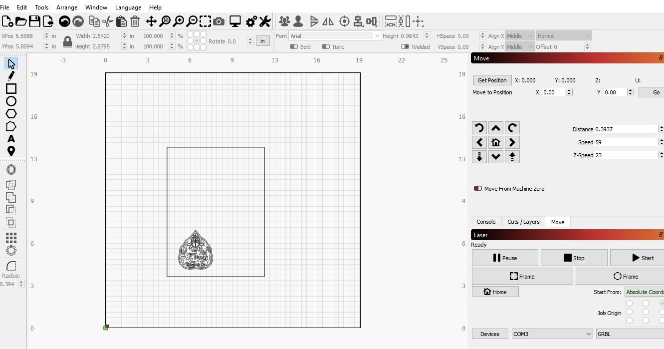
So now I am able to jog the machine around.
As you can see my bed size is 19 X 19
the material that i have on there is 7.25 X 9.625
All I want to do is cut the 2 tones logo that you see in the loser left hand corner.
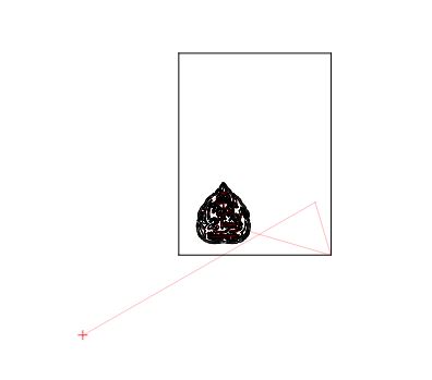
When I run the simulation, I shows the laser coming from the lower left corner of my bed and cutting the perimeter on the material then cutting the logo
The X Y zero will never come on the the corner of the bed.
It will always change based on the project.
How do I control that?
I’ve been watching tutorials every day, but I just don’t see the issues that I’m having.
Delete the box, or just set it to another color, and change that color layer not to output (check box in the cuts list).
Then change the ‘Start From’ to either Current Position or User Origin. If you use User Origin, you have to set what that is. The preview will always show the laser starting from the origin, but the actual job will run from where the laser is, depending on the starting mode you’re using. Read about them and how they work here: https://github.com/LightBurnSoftware/Documentation/blob/master/CoordinatesOrigin.md#coordinates-and-job-origin
When I use my spindle, I can place a piece of wood anywhere on the machine bed.
Then I can locate the X Y Z zero point by using a touch plate.
At that point the machine is zeroed and knows where to start from and go back to when the job is complete. (I can do this virtually anywhere on my machine bed)
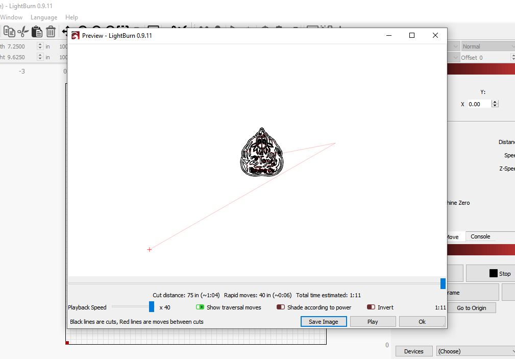
I finally got the green dot to go to where I want the laser to start from and I put my material on a new layer.
However, when I run the simulation, it still shows the laser coming out of the lower left corner of the machine bed.
I cannot have my machine think that the X Y zero is in the lower left hand corner of the machine bed.(I will have a crash situation)
How do I tell the machine where X Y zero start and stop is using the laser?
Look at ‘User Origin’ mode here: https://github.com/LightBurnSoftware/Documentation/blob/master/CoordinatesOrigin.md#coordinates-and-job-origin
Note that it doesn’t actually change anything with the machine, it just remembers that coordinate. With LightBurn, zero is always the machine origin so that you can always jog within machine bounds and the software can prevent you from hitting the rails.
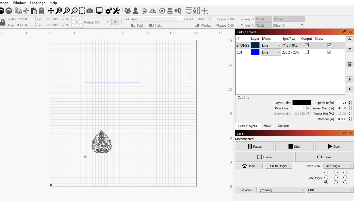
Well for some reason, I simply fail to understand the zeroing of the machine.
So I thought I’ll just tell the machine that my bed size is the size of my material. (7 X 9)
That way the laser will at least start from the position that I want it to.
However, when I hit the start button the machine wants to fast traverse to the upper left corner of my machine bed.
I don’t have half a clue as to whats going on here.
Starting to get the feeling that I’m in over my head.
Did you configure this machine with the latest version of LightBurn, or had you set it up with 0.9.09 or previous?
The current version will automatically set up the macros required to switch you between laser mode and CNC mode, which includes setting $10=0, $32=1, and changing your workspace offset. You can read about these and what they do here: https://github.com/LightBurnSoftware/Documentation/blob/master/CommonGrblSetups.md#common-grbl-setups
The $10=0 setting is possibly what’s causing the issue when you click Start - The software asks the machine for its current position, but if that’s being reported in ‘machine space’ it will be a negative number on your system, so the software is trying to jog to the proper starting spot from there.
It’s worth mentioning that LightBurn was written from scratch for dedicated lasers, not CNC machines, and so the workflow is likely a bit different than you’re used to.
I just downloaded it the other day.
Looks like 0.9.11
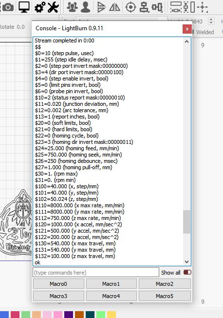
after entering the $$ this is what I get back
I don’t have $=32
On a side note.
The windows will not re-dock once I un-dock them.
The window will not turn blue.
Ok,
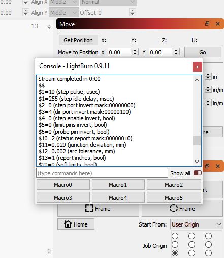
So I found this button that says Current position.
Thought I would try it and see what happens.
Exactly what i want the machine to do.
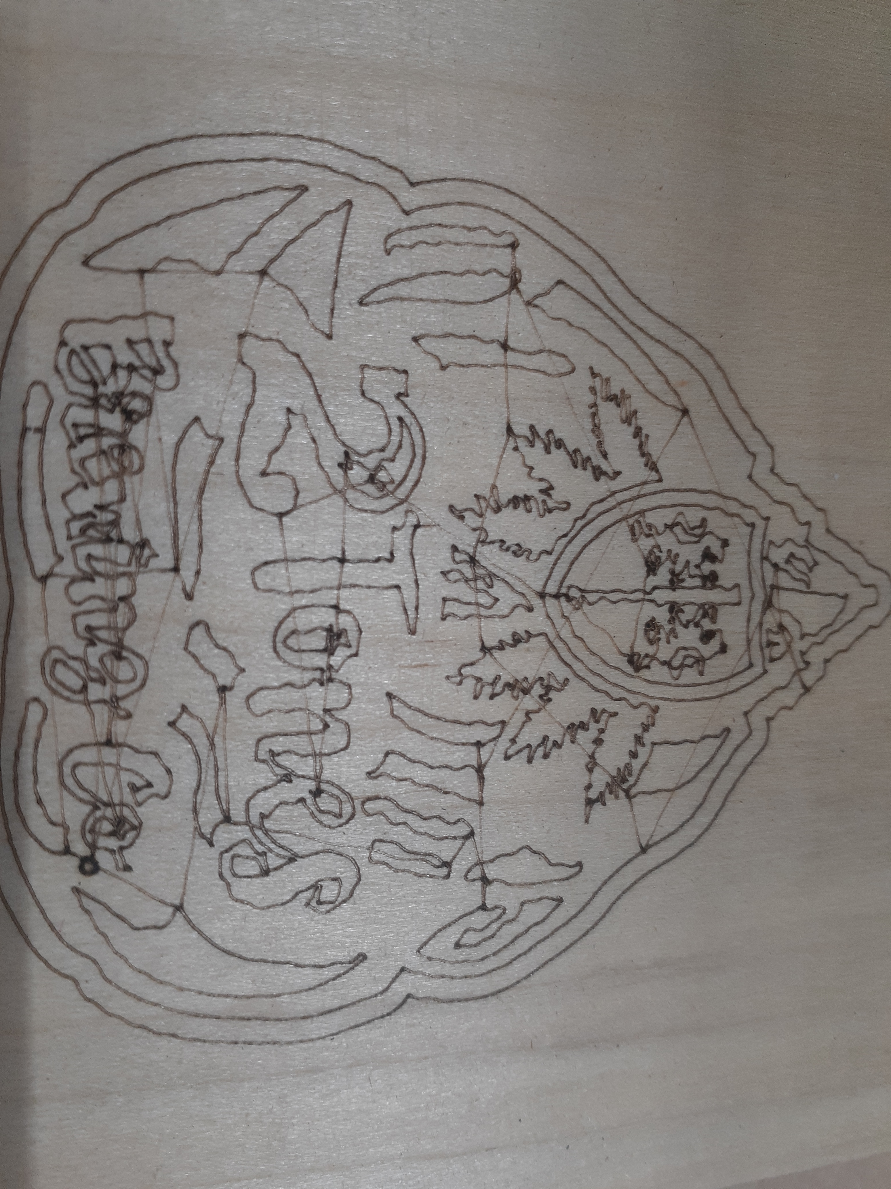
So I ran the program but now Why am I getting these lines throughout the cut?
You’ll need to use the GRBL-M3 driver in LightBurn, as it appears you’re using a relatively old version of GRBL. You will also want to change $30 to 255 or 1000, and alter the ‘S value max’ setting in the Device Settings window in LightBurn to match it.
My guess is that you’re using 1.0c, which is the default X-Carve firmware. It doesn’t do ‘variable power’ meaning it won’t lower the laser output when cornering, but it’ll work ok for basic engraving.
Thanks for the response.
Do I need to upgrade my GRBL?
If so, whats involved in doing so?
You don’t need to, but you’ll get better results with the laser if you do. If you choose to, use 1.1f or later, and save your machine settings before you do it so they can be restored easily. I’m not sure what’s involved in upgrading the X-Carve controller specifically - usually it’s a small command line tool used to flash the new version of the firmware, but I would check with Inventables to see if they have guidance for this.
There is a specific section of the JTech Documentation covering installation and firmware updating for the X Carve. Scroll mid-way down until you see a section that starts,
Set Up Your Machine – X Carve
Ok, now that you have downloaded Lightburn software, we can get started with the rest of the setup. When you install the Lightburn software, you might see Windows trying to protect you. Click on the bottom “Run Anyway” button to install it. The X Carve has some things you need to change to get it all working, so we will cover it here.
When you first run Lightburn, you should have a quick setup wizard walk you through the setup. Here is what you need to do to get it set up.
Thank you.
Today I feel like I’m finally starting to make some progress.
to update your firmware the simplest way is to download t2 laser and use the trial on it to upgrade the firmware, it does it in seconds, I can assure you though that T2 is nothing light lightburn, Lightburn is the Photoshop of laser software so does take time and patience to learn but once you have it cracked you will never use any other software.
The other way to update is is download the arduino program and do it through that but it sounds like you might have problems doing it that way so i recommend the trial on T2. Its the simplest way to do it
A huge thanks To Jay from J Tech Photonics for walking me through the process.
I now have my firmware updated to 1.1f
Lightburn is now showing real promise.
Although I’m very sure that there will be more questions to follow.
1 Like
Ok.
So today I trying to learn about the origin.
I go to a specific place, click “set origin”, then move away from the origin. It is my under standing that this should be X Y zero.
I then click “go to origin” the machine goes in a completely different position Not even close to where i expect it to go.
Any thoughts?
Yes, I’ve gone over these instructions several times.
Keep in mind that I don’t have a dedicated laser, my laser is attached to a CNC machine.
My laser will never come from the lower left corner of my machine bed.
My origin will always be the lower left corner of the material that I place on the machine bed.
That being said, When I do that and then call that corner X Y zero, then move away from the zero, then click on the go to origin button, the machine takes off in a completely different direction.
What am I missing?
You have not said much about how you have this CNC setup configured, technically (I can’t see your settings until you share them ![]() ), so I would look to the following;
), so I would look to the following;
Have you set your machine status reporting to be relative to the workspace origin, not the machine origin ($10=0)?
If your machine uses negative workspace coordinates you’ll need to apply a workspace offset (G10 L2 P1 xx yy).
Could these be issues you are experiencing?