Hi,
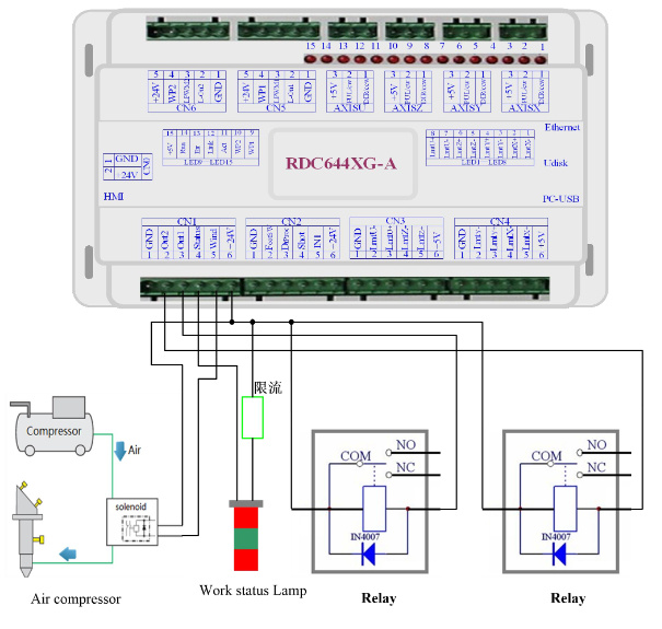
I have provided various outputs of my Ruida with solid state relays.
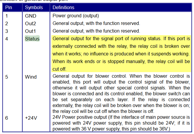
The exhaust air fan is currently connected at the Air Support (Wind) outlet. But it switches off immediately after the job is done. It’s normal too.
Now I would like to connect this relay to Out1 and set a follow-up time of approx. 1 min. so that the fume is completely sucked out.
Is this possible in software in Lightburn? Or maybe a good idea for an update?
1 Like
I’ve already thought on this, but maybe it can also be done with on-board equipment.
If Out 1 can be switched by software, Lightburn would only have to start a timer, the hardware is already there.
Thx is right. Just get yourself a so called timer off relay. You can find them in lots of different enclosures but they all do the same: power off the output after a set time, after the input is disabled. They usually come with dials to set the time and you can even buy the with digital displays. The only thing you need to look out for is to get one which support a input voltage of 24 volts.
They are widely available online, the known China shops, and local suppliers.
It’s not something I can do in the software - I set flags to tell the controller what things to enable, but I don’t have control over the timing. The closest I could come would be to add a set of ‘dots’ at the end of the job that fire the laser at ‘zero power’ for a few seconds.
That would appear to be just part of the job, and if you opened the door while it was still running you’d get the normal warning about the door being opened, it would pause the job, etc - it might be confusing.
Layer with a dot, cut through mode, 00% Power, 1000ms to wait at the end for i.e. 1s
What is the max here?
You could incorporate a Delay On Break (DOB) Relay into your design.
1 Like
Newbie warning: Is LightBurn in control with the OUT1 + OUT2, i tried to use the “Generic output 1” and Generic output 2" in the Cut Settings Editor. But the Ruida 6445G does not respond accordingly.
I did some testing and it seems that:
Output 1: Is activated when the machine is running a program.
Output 2: Is de-activated when there is an error state. (Hitting a limit switch)
Then there is the “Status” pin that should go to some sorts of light indicator. Seem to go active when a program is running, like Output 1.
It would be awesome if the outputs can be controlled with the Generic output setting !
Those were added because I thought they were controllable, but they apparently are not. RDWorks has those buttons too, and changes flags in the RD file, but they do nothing and are noted in the documentation as being “for future expansion”.
Dang it. Was hoping there was a way. Thank you for the quick response. I will stop my design on relying on controlling those 2 outputs from LB. Thanks again.
CN1 Pin 4: This is where you can also utilize a work status lamp. Wire this output to a time delay circuit. The output of the time delay circuit to drive the coil of a contactor.
That looks like the same device that was included with my Thunderlaser Nova 24 laser - it can be set by the user to specify how long the exhaust blower runs at the end of a job.
1 Like
As I wrote above regarding CN1 Pin 4, you could also use this inexpensive time delay circuit (already made for you). Pin 4 to this little circuit’s 24v DC in. Depending on your load requirement, you could either directly wire up to 10A load to the built in relay, or you could have this relay drive a higher amperage contactor (I would recommend driving a higher rated contactor coil with the relay for motor loads).
I mean, it’s a $3 solution. If you need, I can draw you a schematic.
Okay, I also ordered a delay timer.
I took the luxury version for 4 € with LED display 
It is probably easiest at first.
This topic was automatically closed 30 days after the last reply. New replies are no longer allowed.