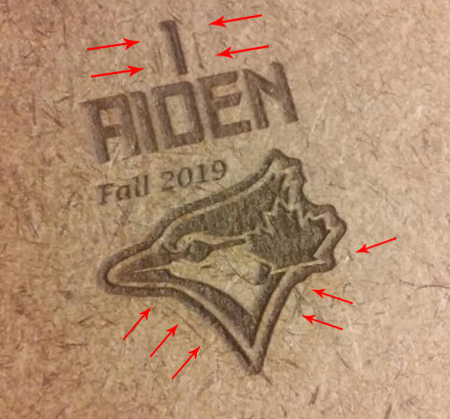
As you can see in the pic I am getting a profile at the edges where the over scan max is.
What causes this?
I have also seen sometimes between cuts where the rapid/traverse moves have a faint line as if the laser isn’t fulling turning off between cuts. Feeling like they are both related.
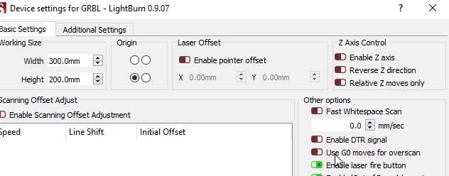
The visible traversal moves between cuts would be the same issue, but that’s very strange - LightBurn uses G0 moves for movement between cuts, so the laser should be completely off. You can turn on G0 moves for overscan in the device settings too, though G1 S0 should also be completely disabling the laser.
So looks like I found the culprit.
I just finished my new 48x48 CNC Router build and learned a lot about EMI using a Spindle and VFD on this build, that got me thinking about my laser wiring…
I moved some wires and the MiniG around (power off) and on the next test it was worse so I knew I was on to something.
When I did the MiniG upgrade I removed all the spiral wire wrap due to all the needed rewiring but never installed it back.
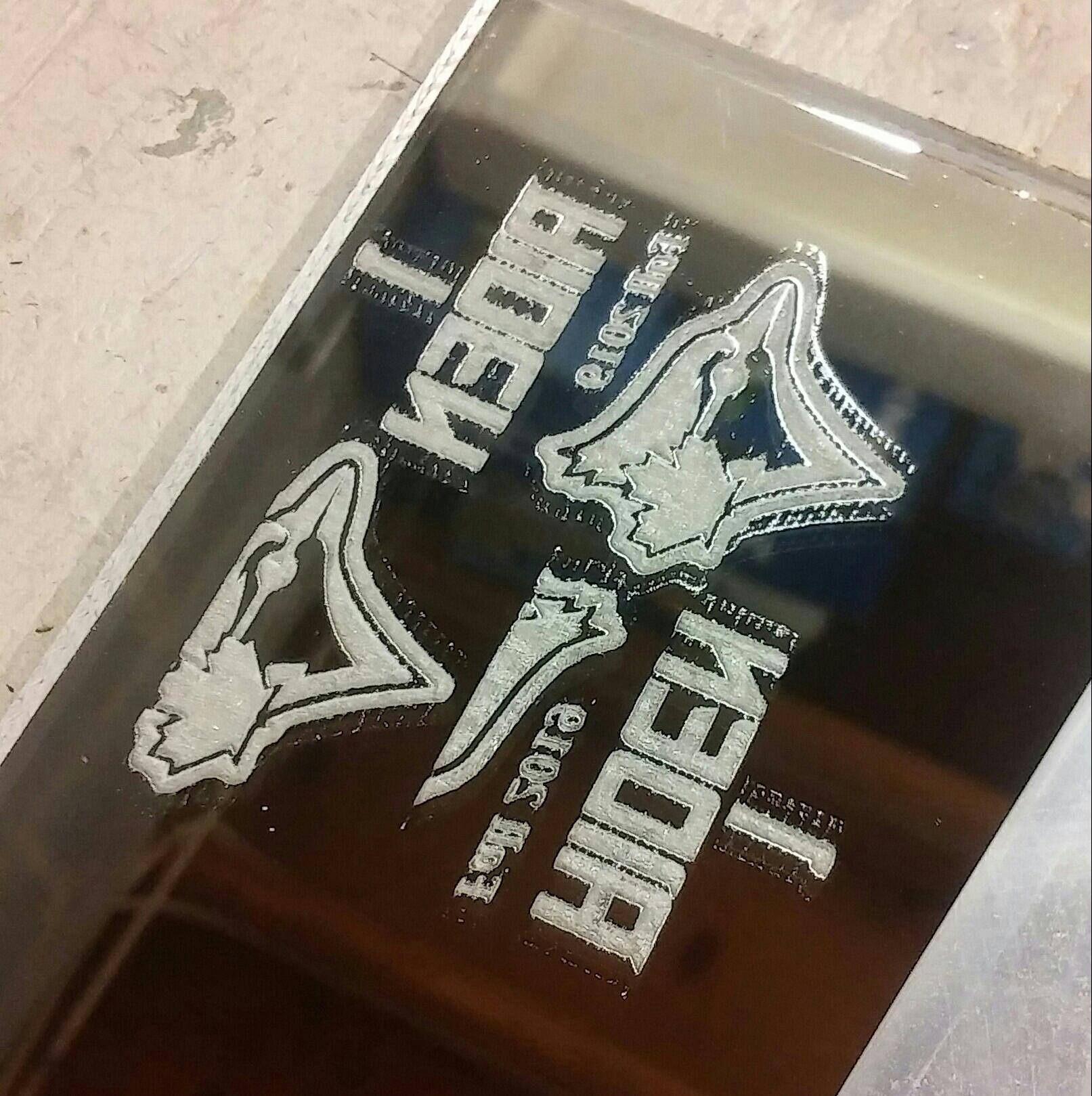
Just now I wrapped all the wiring back up (separate pairs, as it should be) and it has never etched this good! Super clean edges!
Note: for w/e reason Acrylic Glass (backside facing up) will show the smallest amount of lasering that will not show up even on paper etc, thus why I use it for testing)
Glad it all worked out. Also resistance on the big power connector on the mini Gerbil can cause faint lines to appear when not properly seated. So firmly and straight inserting the connector can help too if you encounter a similar issue as above. Ideally the LB software should use M5 (turn laser off) between travelling and lasering (M4 on) instead of just using S0.
I use G0 / G1 because it produces much smaller gcode. During a dithered scan, for example, using M4 / M5 pairs with each pixel would nearly double the size of the emitted gcode, and double number of commands to process.