If it is suitable for you, can you help via ‘‘teamwiwer’’? Can I provide image support? If it is appropriate for you ?
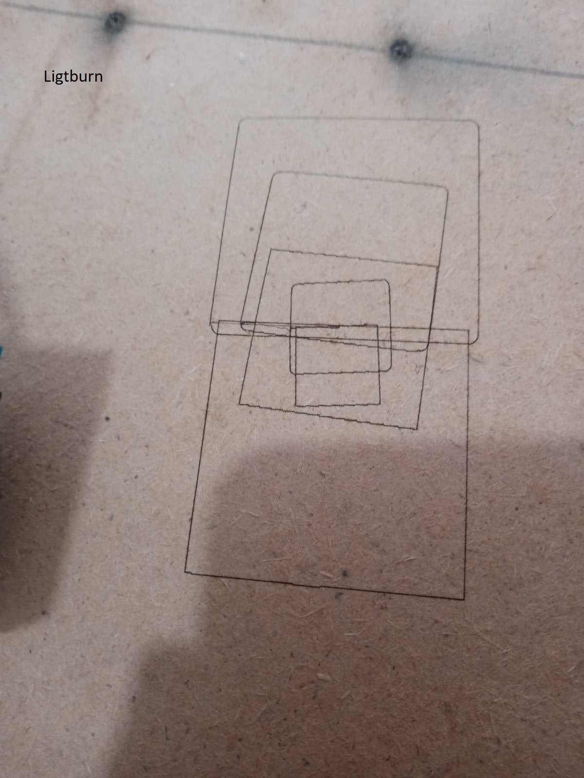
hahaha When I generated gcode with grbl and ran it with ‘ligtburn’ I got printing without problems. so where is ‘ligtburn’ having trouble generating code, what is inconsistent?
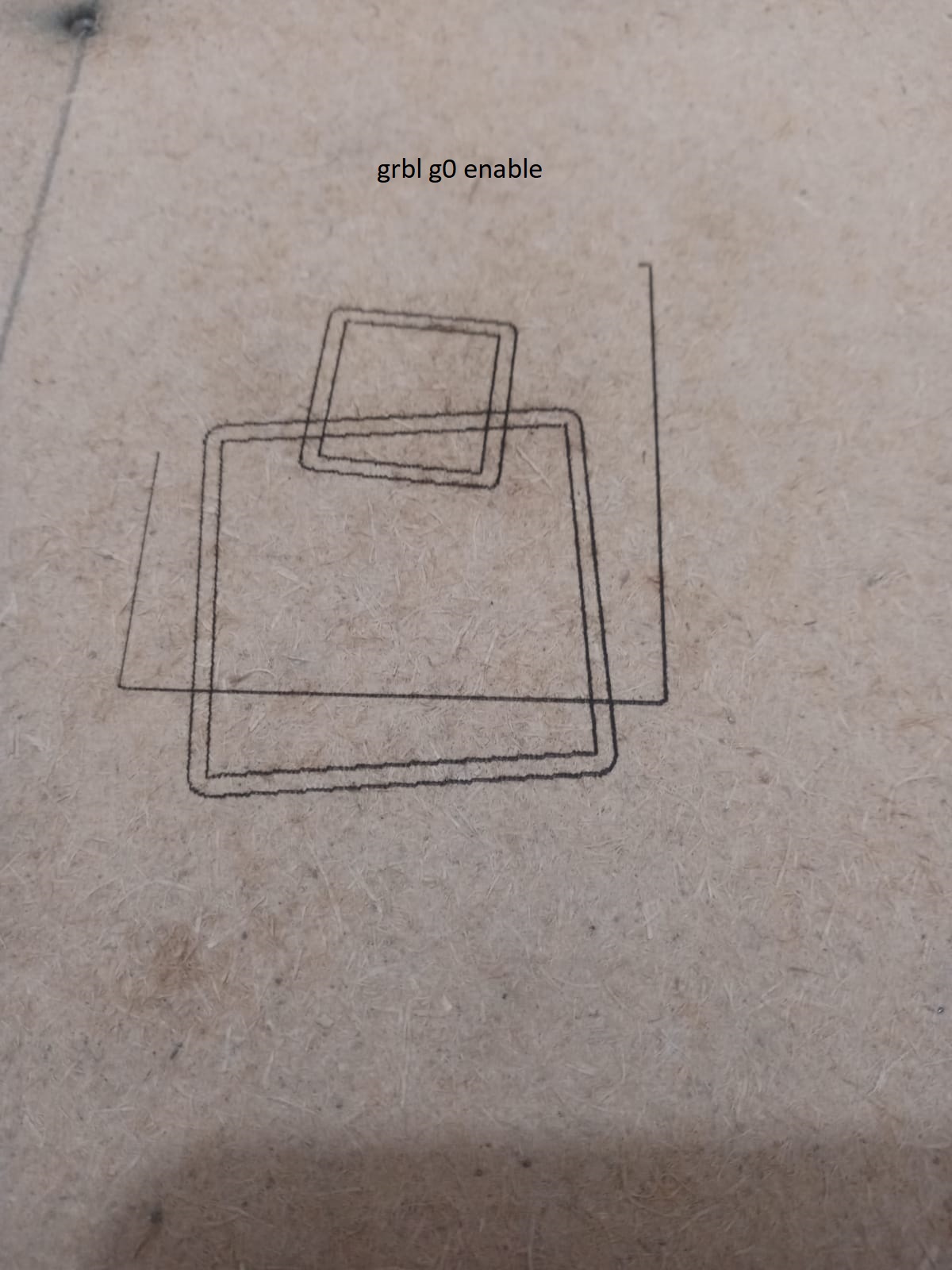
grbl g0 transitions
‘‘G1 X27.12 Y2.605
S0
G1 X27.13 Y0.027
S300
G1 encodes as X26.71 Y-0.019’’ power off continue with g1 action power on and continue
In “ligtburn”, this is the case.
‘‘G1 X0.011Y-0.234
G0 X7.903Y0.041
G1 X-0.2Y-0.335’’
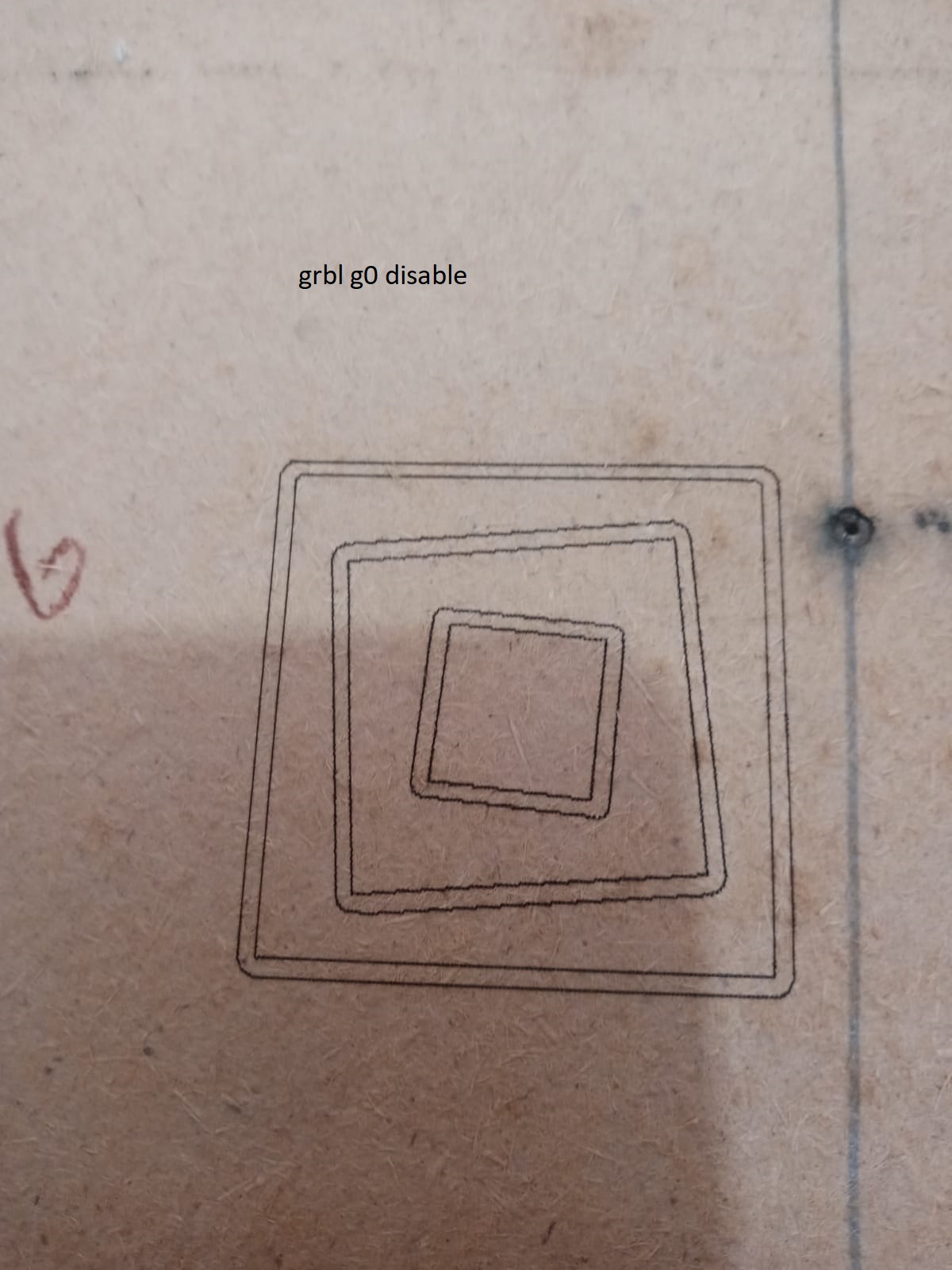
In this form and in grbl settings, g0 is disabled, when it is active, the result does not change on both sides.
The primary problem from what I can see is that the machine is working in combination of positive and negative coordinate systems. This is generating code that the machine is having difficulty with.
I realized that my previous post formatting was messed up and dropped information.
First, can you confirm that the coordinates in the diagram actually match what you identified? Or did I misinterpret your results? This is very important.
Did you run these commands?
G10 L2 P1 X0 Y0
G92 X0 Y0
If so, these might affect the coordinates for the diagram. If so, please create a diagram of the newly updated coordinates or describe them.
The please follow these steps:
- If your machine homes… first home. If it does not home, then turn off, move laser head to back-left of laser and turn on.
- Enter ‘?’ in Console and return results
- Use jogging controls to move laser to back-right. Enter ‘?’ in Console and return results
- Use jogging controls to move laser to front-right. Enter ‘?’ in Console and return results
- Use jogging controls to move laser to front-left. Enter ‘?’ in Console and return results
enter
G10 L2 P1 X0 Y0
G92 X0 Y0
x 0 y 0 ?
<Idle|WPos:0.000,0.000,141.120|FS:0,0|WCO:-110.013,46.775,0.000>
ok
controls to move laser to >> y(-) <<
ok
Akış başlıyor
G21 G54
G91
G1 X0 Y-20 F600 S0
G90
M2
[MSG:Pgm End]
Akış tamamlandı 0:02
?
?
<Idle|WPos:0.000,-20.000,141.120|FS:0,0|WCO:-110.013,46.775,0.000>
ok
controls to move laser to >> x (+) <<
ok
Akış başlıyor
G21 G54
G91
G1 X20 Y0 F600 S0
G90
M2
[MSG:Pgm End]
Akış tamamlandı 0:02
?
?
<Idle|WPos:20.000,-20.000,141.120|FS:0,0|WCO:-110.013,46.775,0.000>
ok
controls to move laser to >> x (-) <<
Akış başlıyor
G21 G54
G91
G1 X-20 Y0 F600 S0
G90
M2
[MSG:Pgm End]
Akış tamamlandı 0:02
?
?
<Idle|WPos:0.000,-20.000,141.120|FS:0,0|WCO:-110.013,46.775,0.000>
ok
controls to move laser to >> y (+) <<
Akış başlıyor
G21 G54
G91
G1 X0 Y20 F600 S0
G90
M2
[MSG:Pgm End]
Akış tamamlandı 0:02
?
?
<Idle|WPos:0.000,0.000,141.120|FS:0,0|WCO:-110.013,46.775,0.000>
ok
I keep seeing strange things. For example, you cleared your offset but then I see one listed in the status message.
Let’s try to do this one step at a time. Please reply to each of these points individually. It’s sometimes hard to follow your replies and can’t tell if we’re on the same page.
- Review this diagram. And confirm the following questions:
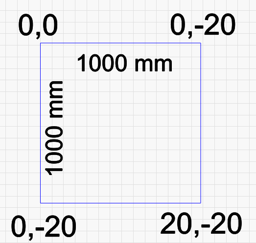
1a. Is your actual working dimension actually 1000x1000 mm? I took this from the device setting screenshot
1b. The coordinates now look consistent. It looks like your laser is setup to have origin at top-right, not top-left. Can you make this change in Device Settings?
1c. However, the fact that max measurement is 20 mm is unusual. Do these coordinates represent the full extreme corners? - Do you have homing switches or no?
- I want to sort out the offset situation. Can you run these commands in Console:
$#
Since I don’t use absolute coordinates, the home button can be dangerous so I disabled it.
As per homing switches, these would be physical switches (either mechanical, photo-sensitive, or inductance types) that when triggered would stop the laser. These are used to allow the controller to reliably locate the laser head and set 0,0 position. Do you have those?
Also, why wouldn’t you use absolute coords?
I realized I told you the wrong thing about origin. After relooking at my diagram it’s not consistent. For your diagram, instead of pointing out relative direction can you put the actual coordinates for those 4 corners? Something is very wrong. Notice that lower left and upper right corner have the same coordinates? Also notice that it only goes to 20.
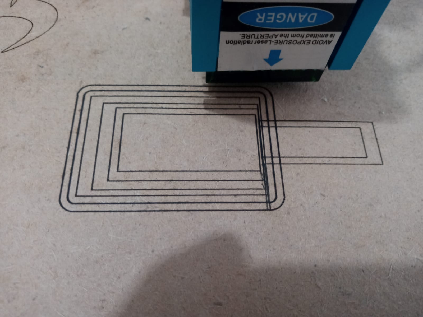
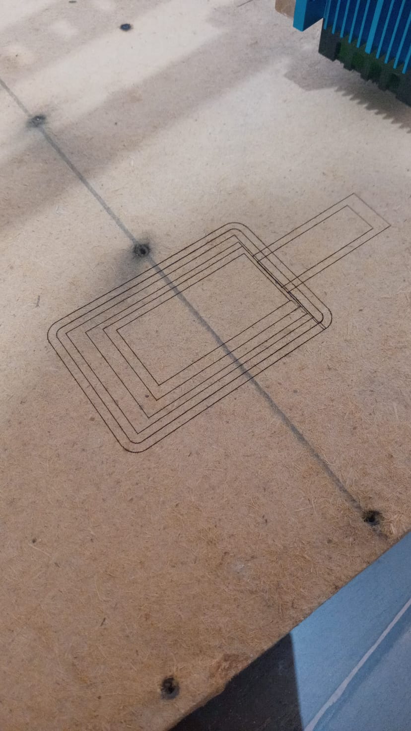
Can you try a burn now and see how it works?
Also, when you do the burn, can you save the g-code and post here please?
This g-code looks okay to me. What did the result look like?
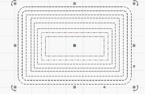
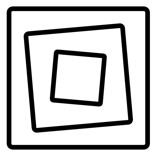
Do you have issues with simpler designs like square inside a square? If so, can you try that and generate g-code?
Turn on laser mode. $32=1
Try again.
I think your laser is skipping steps.
Can you run $$ in Console and return?
$$
$0=10
$1=25
$2=0
$3=0
$4=0
$5=0
$6=0
$10=0
$11=1.000
$12=0.002
$13=0
$20=0
$21=0
$22=0
$23=0
$24=25.000
$25=500.000
$26=250
$27=1.000
$30=1000
$31=0
$32=0
$100=80.000
$101=80.000
$102=250.000
$110=8000.000
$111=8000.000
$112=500.000
$120=500.000
$121=500.000
$122=10.000
$130=500.000
$131=500.000
$132=200.000
ok