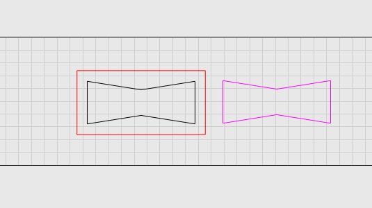
had to alter stock to leave to -1.5mm (black line) to get bowtie to match profile cut out and fit
could this be my machine causing the variance, anybody else encounter this
in future would i be better to try using the inlay function for this type of thing , haven’t used an inlay before hence why i just used profile operations
Are you absolutely positive your tool diameter is 6mm?
You are cutting the black shape from inside, so MillMage is offsetting the shape by the tool radius (3mm) to compensate for the tool size.
You are cutting the purple shape from outside, so it gets offset by 3mm outward, again to compensate for the tool size.
If the tool is not the correct size, the results won’t line up. If your tool was 5mm, for example, MillMage would be cutting the pocket 1/2mm smaller than expected on all sides (1mm too small in total). It would also cut the bowtie shape too large by the same amount.
It’s also worth mentioning that because of the rounding by the tool, the cut-out version of the bowtie won’t fit into the pocket version unless you sharpen out the corners.
yes tool def 6mm , i check all tools with calliper’s to make sure they are what manufacture says they are
yes purple out side, black inside.
I cut the pieces 3 times each using same tool and each time there were different variances, on the black line but purple is exact to what is on screen in mill mage
I’m not worried about rounding in corners , i always chisel them out
The outer line of the left bowtie hole matches the dimensions of the cutout bowtie on the right. The simulation doesn’t have any internal knowledge - it just drags the bit with the specified size/shape around the generated path, so it should be true to size.
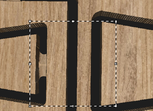
I had to align your shapes vertically, because they were a little off. After doing that, looking at the generated GCode from your file (with the stock to leave removed) I see the following moves:
First move of the Profile Inside:
G0 X353.092 Y94.861 Z5
Maximum Y move of Profile:
G1 X388.039 Y101.374
If I add 6mm diameter of the bit to that first move, the Y goes to 100.861, about 0.5mm difference from the maximum Y value of the profile. Accounting for corner rounding on the inner profile, that’s what I’d expect - it’s not the 1.5mm difference you’re claiming.
If you can generate a GCode file from your project and attach it here, I can have a look at that and verify that the numbers are comparable to mine.
I am not sure if this is the same issue.
Simply testing 10mm finger joints, I am finding that a 1/8" (3.175mm) end-mill is over cutting by about .18mm on a profile cut making the fingers loose. The outer dimension of the piece is out by the same amount (49.64mm and not 50mm).