Reasons to tune my PSU to my tube ratings

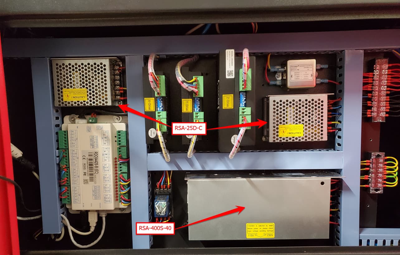
I came to the conclusion that my PS is very similar if not identical to the Cloudray version. In the Cloudray documentation I found the following interesting and a little confusing.
These pics are identical to my unit
.

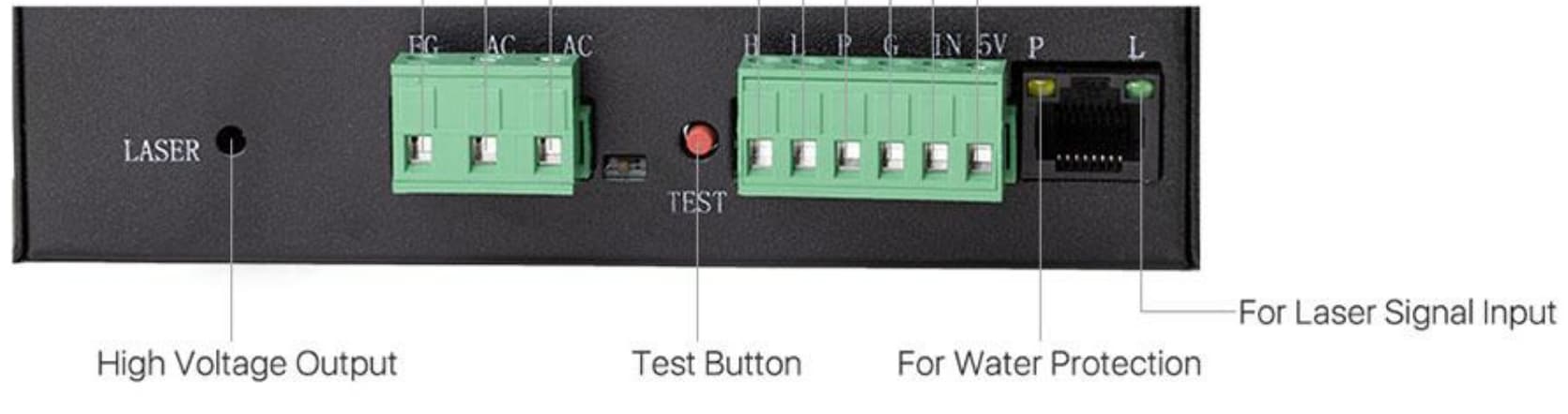
I am not sure what the Laser hole (High Voltage Output) is for. I cannot see anything inside like a pot or anything. I assume that I will be able to use the test button to adjust the current instead of having to get up and fire the laser from the controller?


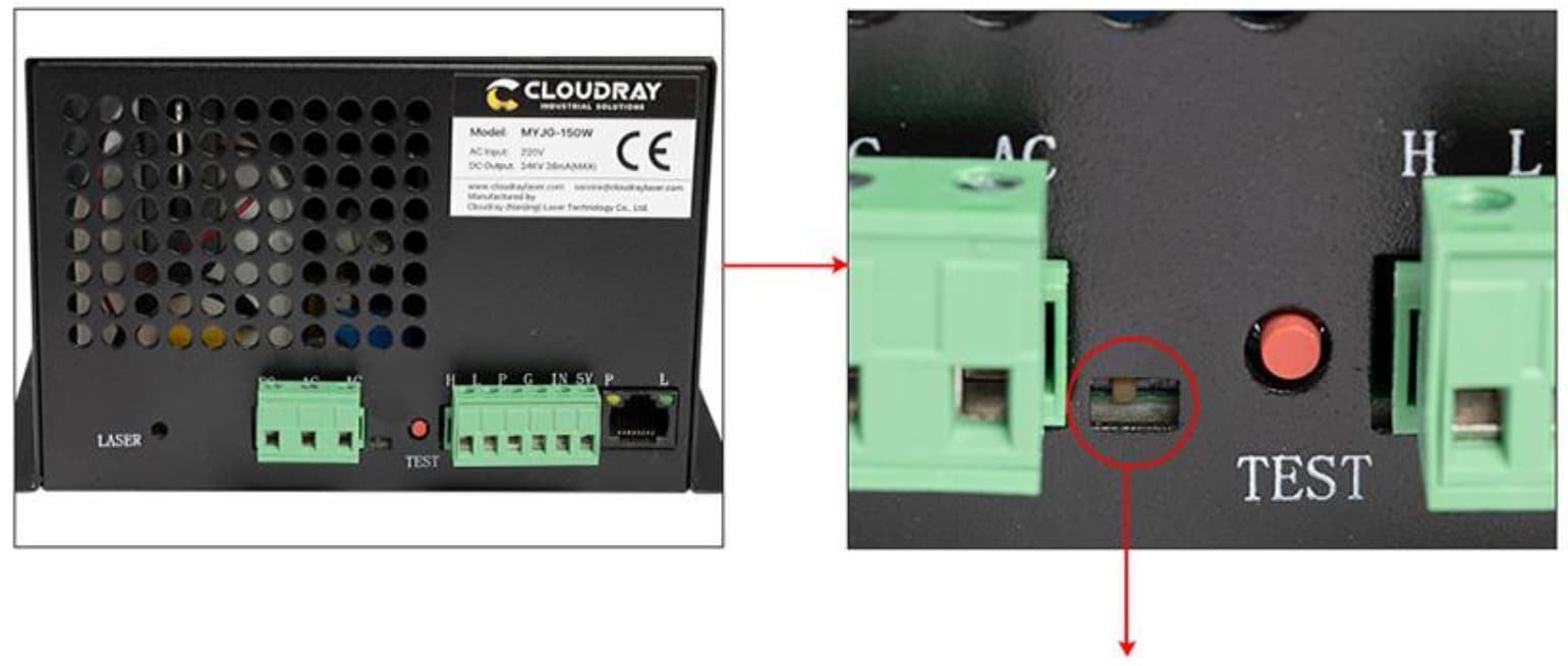
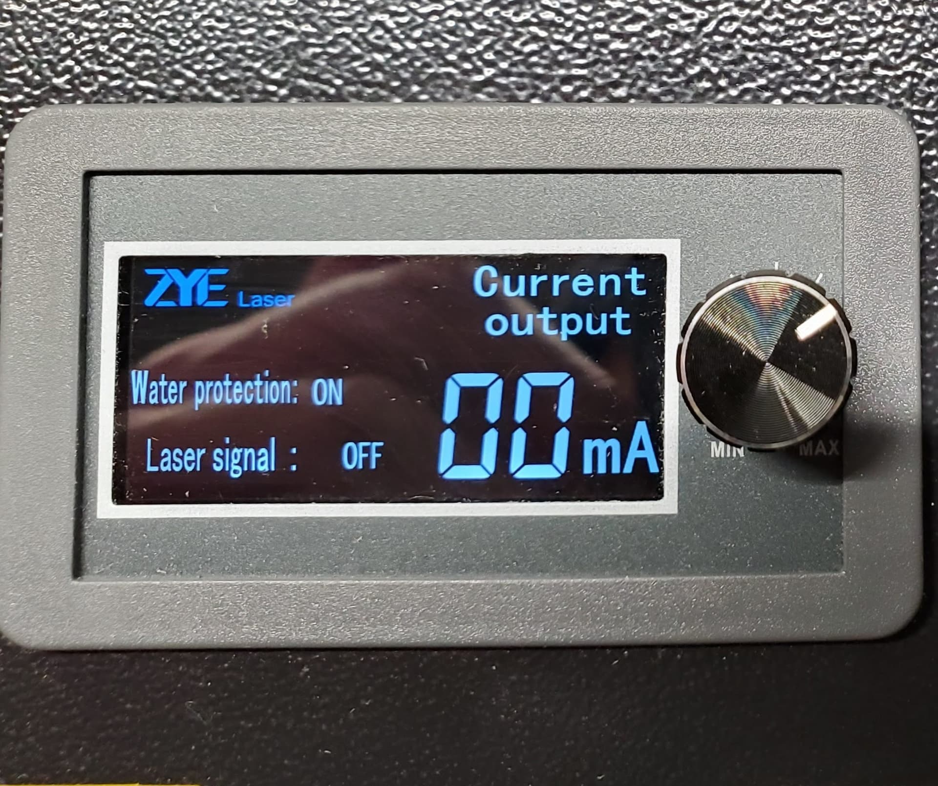
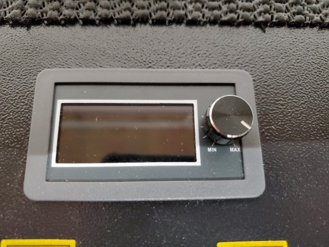
The first two bullet points are interesting to me. I am not real sure exactly what it is telling me. My PS the switch it mentions is to the left. And the LCD on my PS does not appear to have a trimmer potentiometer on it. BUT I do have an LCD screen (see image below) above my controller panel that has a Min/Max dial on it. I am curious if this dial is used to adjust the current? I have turned the dial and it does not appear to do anything but I wonder if that is because I need to move the switch on the PS to the right to make this adjustment?

20231114_152316 (Small)

So does this make sense to you guys? With this information, what is my best course of action? Should I just adjust the pot on the side or is this info providing a different solution?

The apparent assembly quality in that supply is giving me anxiety.

I believe that will change the power for the test button. I don’t know if that changes it for the whole supply.

Typically it would be considered more robust to change at the supply. These type of dial potentiometers are common on K40 type lasers where no PWM power control is possible and are mounted near the front of the machine.

1 Like

Well I went ahead and moved the switch to the right and then started adjusting the max power levels and turning the knob on the LCD and I was able to adjust the current exactly to where I wanted. So I don’t know if this is the best way to do this but it is how it is intended to be done according to Cloudray. I guess time will tell.

Here is the PS and LCD kit from Cloudray.
https://www.amazon.com/dp/B07BBK6LRS/ref=sspa_dk_detail_0?pd_rd_i=B07BBK6LRS&s=pc&sp_csd=d2lkZ2V0TmFtZT1zcF9kZXRhaWwy&th=1

And here is the LCD which has more info on how to use it.
https://www.amazon.com/Cloudray-Display-Current-MYJG100W-Cutting/dp/B082SCWVRX/ref=pd_bxgy_sccl_1/131-2932755-0854752?pd_rd_i=B082SCWVRX&th=1

I wanted to THANK everyone for your assistance. Sorry for my ignorance. I am learning as I go. Fingers crossed everything works as expected :crossed_fingers:

An LED shows when the HV output is enabled, although the supply is typically mounted so you can’t actually see the LED.

The nomenclature definitely doesn’t help. One might reasonably expect a lightning bolt to shoot out of the hole, but that’s not a nominal outcome … :grin:

2 Likes

All three are essentially identical, which noticeably increased my overall cynicism. :person_shrugging:

1 Like

Gee guys, thanks for bursting my bubble :rofl:
I guess time will tell.

Hey I have a question about my other PSU’s. As mentioned above the Laser PSU is on one side of the machine and there are 3 PSU’s on the other side. I would like to figure out what each of those are for so in case I ever have something come up I know what PSU to look at or replace. You can see from the pic that there is a 40V and two 25V PSU’s.

I suppose I can take off the tops of all the wiring raceway and follow the wires but I thought I would see if anyone could tell me definitively based on the size/voltage and commonalities in similar Chinese lasers.

No way to do that, because these things get built with whatever parts are both Close Enoughā„¢ to the original spec and available when needed.

For example, that 40 V supply should be a 36 V supply at its nominal voltage, but instead they used the ā€œwrongā€ supply and dialed it back to the bottom of its adjustment range.

I’d guess those two 25 V supplies are producing 24 V for the stepper motors. You may have two supplies because you also got the Z axis drive, which would draw too much current from the single supply they ship with manual Z axis machines.

But that’s not always true. Adding up the peak current settings for the three stepper drivers in my laser exceeds the single 24 V power supply’s 6 A rating and leaves nothing for the controller and suchlike, but apparently that didn’t justify adding a second supply.

Bottom line: don’t worry, be happy. :grin:

1 Like

That makes complete sense. I have heard and seen how they use whatever they have on hand that is close enough. I guess I will try and track this info down myself at some point.

Thanks

Well I thought I had this PSU tuning figured out but I am a little perplexed today. So yesterday I made the adjustments via the LCD potentiometer on top of my machine. I had moved the switch on the PSU to the right as mentioned in the instructions and then made my adjustments. I was able to get the power levels right where I wanted them. I then shut everything down and proceeded to move the switch back to the left (NORMAL mode). Today when I fired things up I quickly noticed that my settings no longer matched what I set them to yesterday.

Yesterday I had it set where at 99% power I was at 26mA and at 95% power I was at 24mA (recommended continuous power). I did it this way so I would have a little bit more power if needed at times. Today at 99% it was at 28mA (max rating for tube). The strange thing is that it stayed at 28mA all the way down to about 76% (which was how it came from the factory except the factory max was 31mA). At 75% it changed to 27mA and at 65% it was at 24mA (which again was the exact settings from the factory). So the only thing that seems to change was the max power rating came down from 31mA to 28mA but all other levels are pretty much the same.

So then I decided to go in and re-adjust the PSU and see if the same thing happened. It DID! I then went in and made drastic changes just to see if I could get the levels to change. No matter what levels I set, when I switch back to NORMAL mode, it stays with a max power of 28mA and does not change to 27mA until 75% power.

mA Output (Before adjusting PSU)
NOTE: RECI Max Power for Model T style tube: 28mA
25% power = 6mA
50% power = 18mA
65% power = 24mA (Max recommended by RECI for continuous power)
75% power = 27mA
80% power = 30mA
85% power = 31mA
90% power = 31mA
95% power = 31mA
99% power = 31mA

mA Output (After adjusting PSU)
NOTE: RECI Max Power for Model T style tube: 28mA
25% power = 6mA
50% power = 18mA
65% power = 24mA (Max recommended by RECI for continuous power)
75% power = 27mA
80% power = 28mA
85% power = 28mA
90% power = 28mA
95% power = 28mA
99% power = 28mA

I am confused. Not sure if I should keep the switch to the right (where the settings seem to work) or ??? I don’t know if it is meant to stay in PROGRAM mode or must be in NORMAL mode?

Any thoughts?

As far as I know the only difference the switch is make is whether or not to include the trim pot on the panel. Can you not just leave the switch to the right, and still have programmed power? Then just use the trim as an override, e.g. if you notice a job is burning slightly darker then you can dial it back a little on the fly.

As long as you have the dial set to 100% when you tune in the 28mA in your vendor settings (personally I would set that back to 24mA).

1 Like

I have yet to try and run a job with the PSU switched to PROGRAM mode. I will try that shortly.

I am a little confused by your question. So when I made my settings using the pot knob on the LCD, I set the max power in the controller panel to 99%. I then fired the PULSE button and turned the knob. I did this a few times to dial in 26mA. I then changed the max power in the controller to 95% and fired the PULSE button and saw 24mA. That is where I was wanting it.

Now if you look at my pic here you will see where the dial on the pot knob is located in the Min/Max range. There is still quite a bit of room left to turn the dial up. You say ā€œAs long as you have the dial set to 100% when you tune in the 28mA in your vendor settingsā€. I am not following how to do that. Maybe I am missing a step or something. Its not like I have detailed instructions on how to do this correctly. So it is very possible I am doing something wrong.

Wisely is it written:

Any sufficiently sensitive instrument is a thermometer

Does the laser have an active chiller to keep the water temperature within a degree or two of the setpoint? If not, you’ll see similar variations as the tube / water temperature changes with the shop temperature and power levels.

There’s no real spec for the power supply’s regulation accuracy or stability, so a 10% variation is probably as good as it’s going to get.

As @NicholasL points out, the pot on the display is active only when the power supply switch selects it. FWIW, the spare 60 W power supply I got for my laser has a similar remote display, but not the internal switch to activate it. I’m sure there’s a good reason, but they sure haven’t told me. :grin:

Last time I tuned in power on a machine with one these displays and the dial I don’t recall even noticing that switch so I’m guessing it was already set to the right. So the steps I took were (from memory): (example if aiming for 24mA) :

  1. Set Max power % in Ruida vendor settings to 100
  2. Set the dial to 100%
  3. Set pulse power to 50% at the machine panel
  4. Use the ā€˜Pulse’ button, read the mA value
  5. Trim the HV PSU until the current reads about 12mA
  6. Set pulse power to 99% at machine panel
  7. Use the ā€˜Pulse’ button, read the mA value
  8. Trim the HV PSU until the current reads 24mA when pulsing.

That’s it.

And if you prefer not trim the HVPSU directly, the steps would be like this:

  1. Set the dial to 100%
  2. Set pulse power to 50% at the machine panel
  3. Use the ā€˜Pulse’ button, read the mA value
  4. Adjust the Max power in Ruida vendor settings so you are at roughly 12mA
  5. Set pulse power to 99% at machine panel
  6. Use the ā€˜Pulse’ button, read the mA value
  7. Adjust the Max power % in Ruida vendor settings until a pulse reads 24mA.
2 Likes

So the first option requires me to adjust the pot on the side of my HV PSU, correct? I just wish I had confirmation that that is the correct pot.

From my testing when I set the max power in the vendor settings, I realized that the pulse max power will be capped at whatever the vendor settings are set to. Meaning that if I set the vendor settings to 65%, then the max power I can set on the pulse max is 65%. I was thinking that no matter what the vendor settings are set to, the pulse max power would still be adjustable from 0-100%, but it would reflect the range of power designated in the vendor settings. But whatever works I guess.

Thanks for the info. I will look at this tomorrow and determine how to proceed.

Yeah all these min/max power settings between machine and software’s get quite confusing. I hope it was understandable.

Yes I have a 5200 chiller.

I may come to the conclusion that the LCD pot knob is more trouble than it is worth and just go a different direction. We will see.

Thanks

Tubes usually have a current rating of maximum working current and a do not exceed rating. Whatever your tube, you should be able to run it at that maximum working current normally. Meaning it’s not really a good idea, but ok when you need it light duty.

If you require 50W all the time for your work, then I think you’d be foolish to buy a 50W machine…

The do not exceed rating or absolute maximum, indicates known damage to the device, in this case the gases actually break down at that current level … at a greatly increased amount.

I cringe every time you post that you are pulsing it at 31mA… If it lases at above the 28mA level, it’s damaging the device. The last comment in post 6 I pointed out my interpretation of your post.

There is no short pulse when this occurs, it happens like lighting… Many of us refer to the lase in tubes as lightening in a bottle, a very close analogy. Anytime it lases at these current ranges, it damages the device. The longer (more pulses or time) the more damage… it’s additive and does not recover.

If you’ve pulsed it twice for each post, which is probably conservative, that’s over 100 times…

I have to say something as I think you are irreversibly damaging your tube.

Setting up anything, it’s proven that a conservative tactic is the safest approach.

It’s not necessary or recommended to drive them at their limits and especially above their know limits in the setup/test phase.

Problems can be found and corrected at less stressful levels to the hardware.

We really don’t know how these are wired, but I suspect it turns the lps into a dpssl type operation and the pwm is routed to the L terminal… for this to work, the lps has to turn on/off at full power. This is how dpssl, rf and to a similar extent, how fiber machines operate.

I’m speculating … it appears to me the same mechanism they use on the K40 with the pot controlling a maximum value and the pwm is switching it on/off.

If @ednisley has one of these meters that plug into the lps, he could confirm my speculation as the current should never change relative to a change in pwm rate with this configuration.

I’ve always wondered how this is supposed to work. It seems likely that the switch changes the IN input to the pot and the pwm to the L. That would be relatively easy to do.

Good luck

:smile_cat:

1 Like

I only pulsed at 31mA three times before I my PSU adjustment which brought the max down to 28mA. Yes I understand that that has probably shortened the life.

The crazy thing is, the person/company I purchased it from felt I should have just ran it with the factory settings. But I am just glad I had the thought to check the PSU power (which was before I learned all this) before running any jobs.

Thanks for the great info.

I do, but 60 W power supplies lack the ability to use the external knob: it’s just a decoration. :mutter:

Absent any relevant schematics, I think the switch in the power supply just replaces the internal trimpot with the external one. Twiddling the external pot would then adjust the maximum tube current, just as the internal pot does, with the rest of the circuitry unchanged.

Having front-panel adjustment able to crank the current beyond the tube spec seems to make an inadvertent Bad Outcome far too likely and isn’t something I’d want to have around.

1 Like

I agree.

So if this were the case, then these steps that @NicholasL posted would not necessarily work as intended, correct? Trying to wrap my head around this. Hmmm

Here is my thought process on this. If the switch just changes which pot is to be used to adjust current, then can one (PSU pot) pot fine tune/adjust the other pots (LCD pot knob) power range? Does that make any sense? My understanding of his steps is to set the LCD pot knob to 24mA at Max (100%) by adjusting the PSU pot, so that even if the knob gets bumped or changed it would never go over 24mA.