No, when I was double checking the connection I made sure the PWM and GND were connected to the same wires in the new as the old, the keyway helped with confirming that.
I’ll trace back the wiring to double check. I’ve ordered a replacement multimeter as I’ve been unable to find mine. It should arrive tomorrow so I can double check the voltages.
1 Like
Well, apparently something isn’t right.
@jkwilborn I traced back the wiring as far as I could without removing the housing from the primary control board. All indications show that the wiring is fine, every connection reflects the same connection in the flow. PWM to PWM to PWM, GND to GND to GND, VCC to 12V to 12V. I feel confident that the wiring is fine at the primary control board as the old laser module worked fine until it died.
@berainlb I tested the PWM and Ground, maybe I did it wrong. I can’t say as I’m an electrician. I unplugged the laser control wire from the module and ran an etch process through LightBurn with 3 squares on 3 layers set to power 0%, 50%, and 100%. The voltages I was getting with the black to GND and red to PWM were 0.0±, 1.5±, and 3.0± respectively.
These aren’t quite the voltages I would expect to see but at least they are varying which should be enough to get this to work at least in basic.
I’m actually quite surprised it’s not working. There shouldn’t be much more to this.
Try one thing. Can you test the PWM and VCC voltage at the end of the cable? Wondering if the cable has possibly gone bad.
I’m guessing Volts, and +/- meaning close to it, these actually are the right voltages for PWM.
Most controllers nowadays are 3.3V logic. So 50% PWM will be around 1.5V Assuming your meter is kind of RMS DC meter.
What about power?
I’m agreed with PY on the other thing: check again at the laser end. These cables most of the time are not high flex but regular hookup wire. If you have some mileage on your laser - it is possible that cable is worn, broken.
What is your $31 settings? What kind of controller? Anything other than zero can cause trails on some controllers.
Can it be that this laser just unexpectedly too powerful?
At what speed you are trying to engrave? I have LaserTree 20W (4W). It is slow to turn on but shuts down in instant. On mine I can see timing related artifacts at speeds exeeding 1000mm/min. It is easy two screw-up integrator circuitry for power control. Maybe you running just too fast for that particular laser? Try slower/less power.
$30=1000
$31=0
$32=1
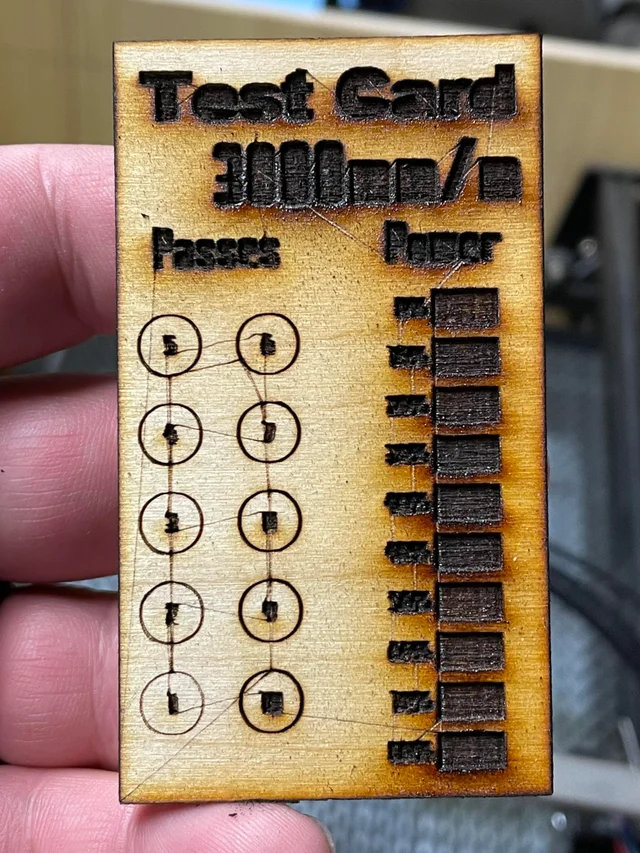
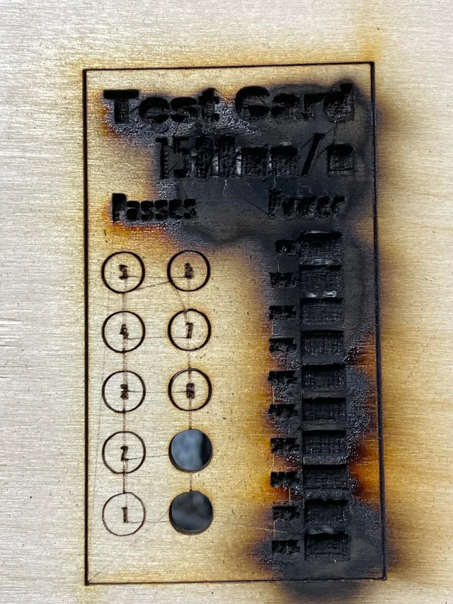
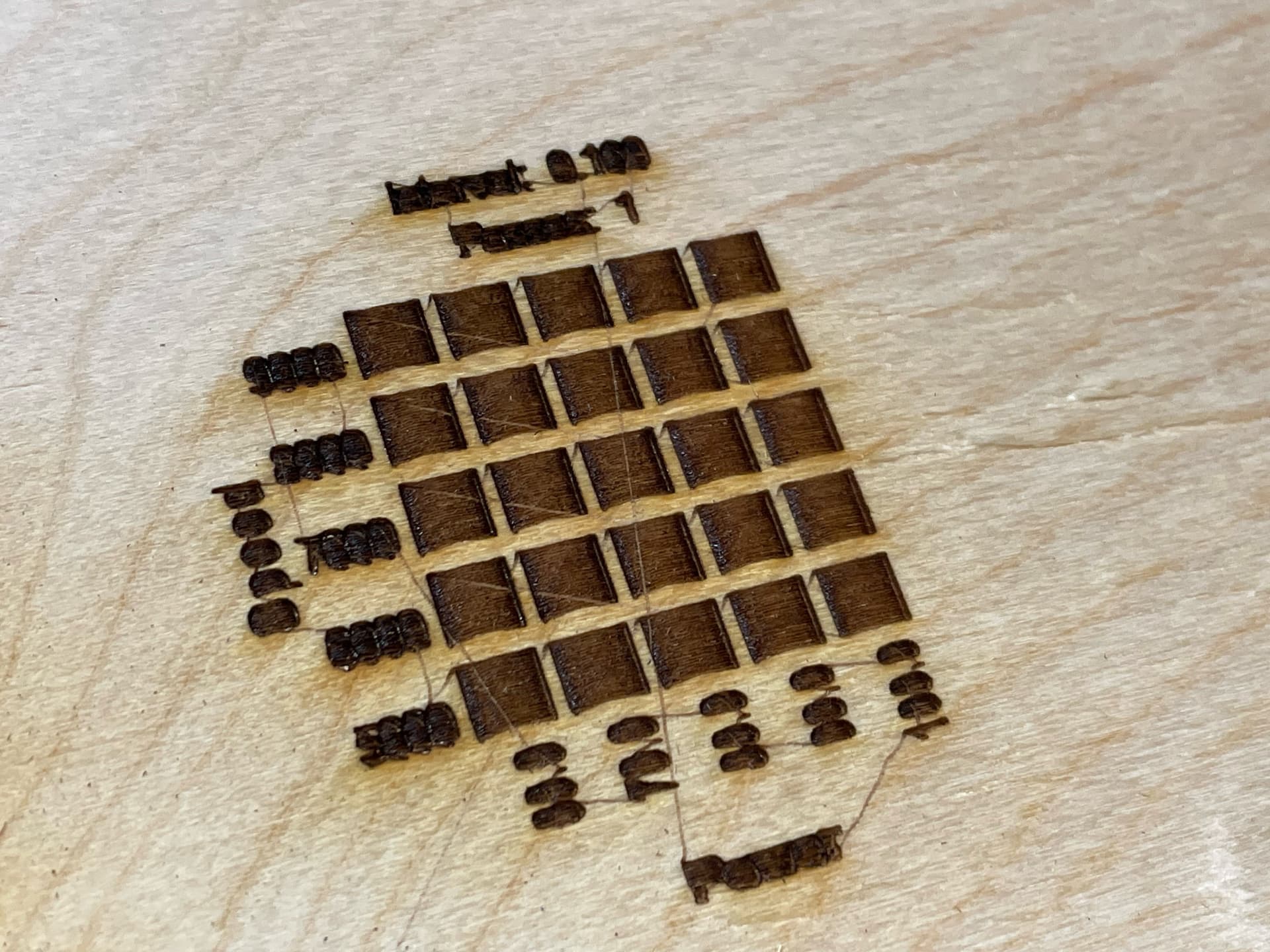
The controller is an Ortur Laser Master 2 (not LM2 Pro, the original). The original laser I got with it isn’t spitting enough power to even scorch my 3mm birch ply. Slower speeds do not remove the path line, they “enhance” it.
Here are some tests I did so you can see what it’s doing…
@berainlb Checked both ends of the wire and the voltages were the same, connected everything back up and ran the engraving with the step motors disconnected so I could check at the solder points of the module and I was getting 3.0± volts coming off the PWM connection for 0%, 50%, and 100%. I think there has to be something wrong with the driver board, but what are the chances I had the same problem 3 times in a row?
You’re saying that without the laser module connected you get normal voltage readings but you get solid 3V for 0, 50, and 100% power on the module itself?
That explains the actual output you’re seeing but now the question is why…
I don’t think it’s likely that you had the same problem 3 times in a row… I think there’s something more fundamentally wrong. I don’t have a good hypothesis for why you’d be seeing 3V specifically though even for 0 and 50%. It’s not clear to me where that would be coming from in the 0% scenario.
In any case, I suspect your laser is just firing at full power the entire time the laser is engaged.
Looks like laser never OFF.
Lets clear the facts a bit:
In message 23:
In message 29:
Are both statement ture?
What is the difference of test conditions? Is that first one without laser connected and second one with? If so - your laser PWM input is blown short to logic VCC. Change the laser. I can guess that at one point, in message 18:
If you did connect 12V to white/PWM wire at some point - this is it, PWM input on laser is blown.
This is likely small gate chip, or even a transistor. Would be fixable. But if you have no clue then you will need to replace that laser.
I don’t think this would harm it… Many of them are allowing higher voltages on the pwm pin… so does mine.
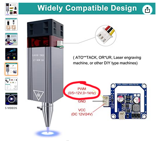
here is his laser
![]()
There is some miscommunications here. This should have been solved quickly.
He has a control board, if he learns to drive that, it may help us fix this. I’m not even sure what he’s doing now.
![]()
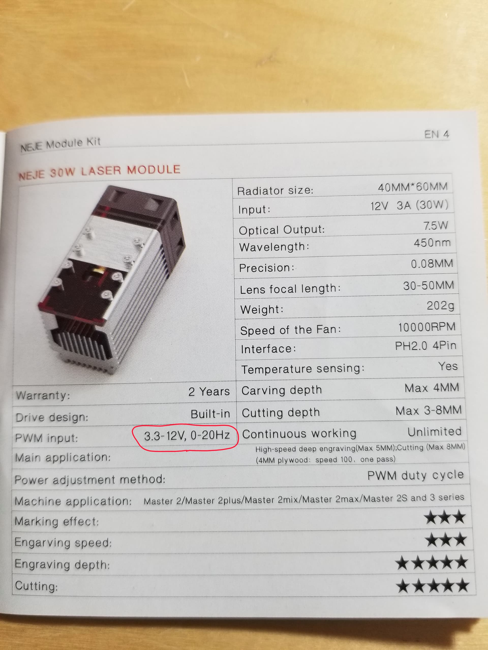
I have to admit that with such specific reference to the spec - Jack is right, 12V on PWM should not have blown it.
Then there is another interesting detail: max F = 1KHz. This is default for original GRBL. FluidNC default is 5KHz. Is it possible that PWM integrator is choking on such low frequency? I set my F on DLC32 to 10K, it is quieter and smoother (gamma/linearity changed a bit but not bad).
1KHz is lower end of them all.
New question: what PWM frequency “Ortur Laser Master 2” is running at?
My earlier question still not answered: There is a discrepancy between post 23 and post 29. What is the difference?
I doubt there’s an issue… This is the specs on mine… it has a relatively slow pwm rate. Some of these documents you have take with a grain of salt…
I know I’m not running at this speed ![]()
![]()
Staring at that laser spec: “0/5-12V”. This is not common way to express the range.
Does it mean that 0V for off and 5-12 for ON? Then 3.3V logic output that Ortur wil lnot reach threshold of 5V. Will need level shifter/buffer.
Is there a full manual and the detailed specs? Should we RTFM it? For the laser. Controller is obviosly 3.3V. Or is is? Another manual?
Is it a signal level mismatch?
Jack,
I’m very certain they meant “20KHz”. With upper limit of 20Hz you will not be able to use it with any real controller.
But you see - your can take 3.3V logic, so is every laser I have. Eric’s laser I think need 5V minimum for control.
This stuff generally works… So I’m still thinking it’s not the laser…
If the 5V was required, it would never lase except for the 12V being on it and I doubt the PWM could power the laser in that state so I’m dubious it’s lasing with the wires crossed.
Most of these specify around 3V, but I have no idea what the input circuit is for these…
Mine works off the 3.3V pwm voltage…
I specifically buy mosfets that switch at 2.75V just because of this…
![]()
But spec is a spec, and best of my comprehension it says need minimum 5V logic.
Can you interpret that spec differently?
It’s good you know when to ignore the specs… like for my 20Hz pwm frequency … you wrote that off quickly…
Maybe you’re right… that would be sad…
![]()
It just strikes me as very unusual number.
… more thought on 12V max on PWM input: That might be safe only when there is 12V power applied. Those kind of inputs usually clamped to the VCC. If there is no VCC then clamp diode can blow, making short to VCC, thus always ON.
This is assuming that Eric did at one point swapped the power and PWM. Though I’m not certain, but it does increase possibility that PWM input is blown.
Schematic for that laser driver board would help.