Replacement head for the A5 pro 40

Does anyone know if there is a plug and play replacement laser head with more power than 5w?

When you buy a more powerful module, don’t forget the power supply.

Atomstack now as their “M50” module ( Amazon.com: ATOMSTACK M50 50W Double Ultra-Fine Compressed Spot Laser Module W/Gyroscope, 10W Optical Power, Fixed-Focus Laser, Engraving Speed Higher, for Laser Cutting, Engraving Machine, CNC, DIY Laser). It costs about as much as the A5 Pro does, but I just picked one up and am putting it through some tests. Off the cuff so far it is a significant upgrade in ability, at a price.

Thanks guys, good information.

lbeser, Did you have to use the included power supply? Or was the a5 pro connection adequate? I assume you had to use the included adaptor board as well being as it has a four pin, but the A5 has a three pin or did you just replace the plug with a four pin three wire plug? I have one now and want to put it on my A5, but I want to do it right.

I recently looked at the current requirements of the M50 and it was just below 3A for normal usage and higher than 3A at peak usage. If you add the requirements of the controller and steppers you’re looking at 5A to be safe.

So assuming you have a 5A power supply and the controller can handle that much current then you may not need a separate supply but this will depend on your setup. I’m not familiar with what the controller in the A5 can handle.

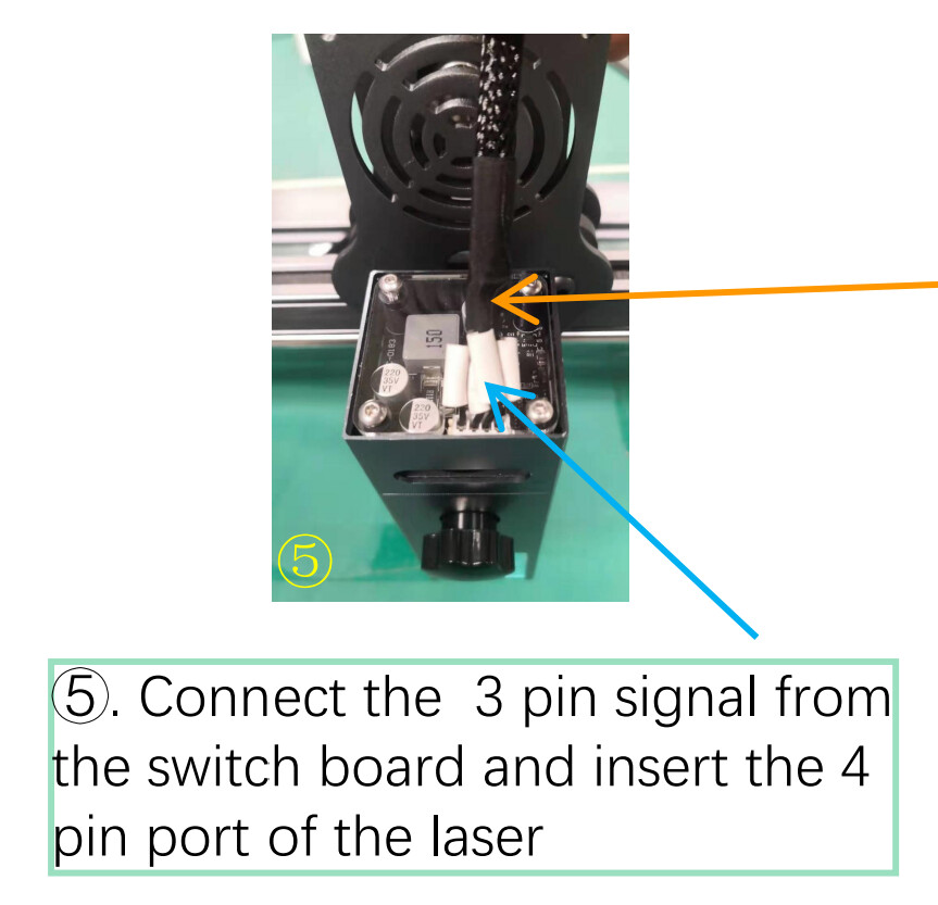
This is a little bizarre but they have you plug from 3 pin signal on the interface board to the 4 pin on the laser so it looks like it’s not even being used. If your controller can handle the power draw then seems you could use the same cable to connect directly.

My A5 pro came with a 12 volt 5 amp power supply and the controller SHOULD be able to handle that much power. Looking at the X7 Pro, it has the same rated power supply and uses the same controller while using the M50, all should be good.

In all actuality, adding the adaptor card on the carriage is more of a nuisance then anything else, but seems OK if I don’t want to swap connectors. It shouldn’t affect the power at all

Sounds like you’re good to go then. Let us know how it goes.

Hi chillerman01,
did it work to run the M50 on the A5/20W without the adapter board?
I´ve got the same thing, but I´m not shure which pin will not be needed.
The 3 pin plug from the A5/20W controller mechanically matches on both sides of the 4 pin socket of the M50 module, left and right, but which is the correct plugging? :slight_smile:

While it works without the second power supply I found it needs the second one to perform at the power rating of the lasers. Not a big deal but the upgrade was certainly worth it.

I agree. I have it installed and, like you said, I think it is not getting the full power capability. It is a great improvement and I can cut things with less passes and thicker materials as well.

How are you running the power cord? Just run an extension cord up next to the machine? Kinda wish they either gave us a longer power cord or a longer connection from the board to the laser.

Check the markings on the controller and laser module. Make sure you’re matching the markings on both sides +/GND/PWM.

1 Like

I attached the brick to the arm of the stand it’s on with velcro, and run an extension cord over to it. KISS rule.

Hello all,

I bought the M50 to upgrade my Atomstack M30. The website indicates that the M50 module is compatible with ANY Atomstack unit. However, aside from the previous comments regarding he 3 pin vs 4 pin connections, when installed, the M50 module makes contact with the front rail BEFORE the unit reaches the Y axis limit bumper. I realize this can be offset in the controlling sw, but is this really how it was designed?

I’m not sure about the specific M30 → M50 swap but from what I’ve seen compatibility doesn’t necessarily mean direct swap-in replacement. In this case it probably means electrically compatible and possibly same mounting holes.

Is the laser module impeding clearance from a different thickness or height? You may be able to raise the laser module to get the necessary clearance or else relocate your switch.

Not sure how you would do this. There wouldn’t be a great substitute for triggering the limit switch.

Good morning…thx for the assist.

The module makes contact with the front rail regardless of it’s height…resulting in approx 3mm less working area. I’m not concerned with the 3mm, it’s that the module is touching someplace where I don’t think it should be, possibly resulting in damage to the module. There is no limit switch, it’s a simple post secured into the side rail that prevents further movement in the “reverse” Y axis.

Here you can (hopefully) see the problem, and while it’s not the nbest view, the laser module in the background is touching the front rail.

By “offsetting it via the sw”, I mean that I can adjust the “origin”, thus starting working point, and physically adjusting the project in the useable working area to negate the ~3mm.

Got you. I didn’t think this model came with limit switches so was curious why yours was different. Are you able to replace the post with one with a larger diameter?

It’s possible that you could still get the full current Y travel even with the loss. Usually there’s a margin of error included that might give you enough room. But will depend on your specific laser.

I placed a cable tie around the pin with the lock towards the Y axis arm to simulate/enlarge the pin, seems to work ok for now, but yes, I’ll explore something more solid in the future.

As for the full Y axis travel, with the larger ‘pin’ it prevents that, which I’m ok with as long as I know it’s inaccessible and account for that in my projects. With the reference grid I’m burning now, that’ll hopefully prevent me from placing something in that area.

As far as the power…I don’t have the extra PCB plugged into power, but the laser seems to be running fine as is. I don’t have a laser power meter to measure what I’m getting w/o that extra power, but as long as it burns what I’m doing now…

I’m waiting for Atomstack support to get back to me, but I’m not holding my breath.

Thx again for the wisdom.

Are you not starting the laser with the laser module in the front left? Where do you have your origin configured in Device Settings. Believe that should be front-left. Where you should be “losing” space is on the top of the bed. Or rather, running into the back of the bed. Easy remedy is to reduce the vertical work area in Device Settings in that case but assumes your origin is at front left.

I ran some calculations on the M50 earlier. I think it claims to draw just under 3 Amps in normal operation and over 3 Amps at peak. This means you should minimally have a 5 Amp power supply but comfortably 6 Amp. If your power supply for the controller can supply 6 Amps you’re probably good but that’s a lot of current going through the controller. It’s probably designed up to 5 A but will be curious what Atomstack comes back with on that. If the supply is rated less I’d suggest using the adapter board and providing separate power to the module.