Well i tried this method with a 16" x 16" square and she is off 1/4 of an inch. This weekend cant come by soon enough, I will utilize all the knowledge that has been passed on to me in here. Patience and time will get her back to square
Alright. I took the belt off and squared the X and Y. That did the trick. BUT!
I did notice how this happened in the first place. If you look at the images a few posts prior. Standing in front of it. If I bring the gantry all the way front, the machine does not have a limit sensor. So this let the machine keep trying to go. When it did this, the 2nd mirror hit the slanted front frame causing the belt to skip out of square.
I figured this out because I did it after I squared it. My home is at top right, but I always like working from bottom right, I guess I never notice it came that far forward.
I now have set markers i front so that I do not exceed this boundary.
I thank all who helped and shared their knowledge.
If you use the console and you can run the machine out of bounds, there is something amiss here.
Once the Ruida completes the boot, part of which is the ‘home’, it will ignore the limit switches. It knows where 0, 0 is and therefore knows not be go out of the defined ‘work area’.
If it homes properly, you should not be able to run it out of bounds
If I’m understanding you…
Seems odd you’d like the gantry and carriage where you have to work ‘over it’… Most like the machines ‘moving’ parts at the back, so all the hardware is out of the way when dealing with the setup/material change.
Can you comment on…
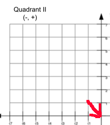
The Ruida is configured to ‘home’ and operate in this quadrant
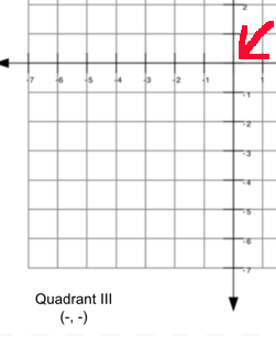
But your driving it like it’s in
I’m sure that adds complications… ?
I’d expect you image to be mirrored across the X axes.
Good luck
![]()
Your illustrations are right on.
With the machine being so big it feels normal to have “my” start point in the lower right corner vs the true home of the machine, top right.
For now I have set some blue masking tape on the bed to show me my limit. A few inches less then when it would crash.
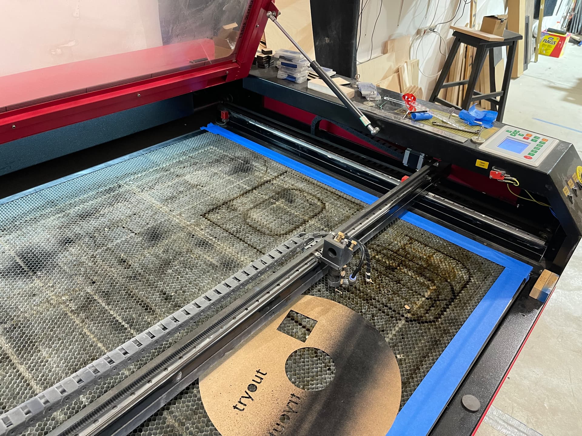
I will upload some images, but with the previous images the front of my machine is not fully square, it has a 45 degree slant and that’s where the mirror crashes because there’s no sensor or the controller doesn’t have a limit set for that direction.
Are you running without a ‘home’ on that axes?
Pictures would be good. 45 deg seems pretty radical for a part in a laser…
![]()
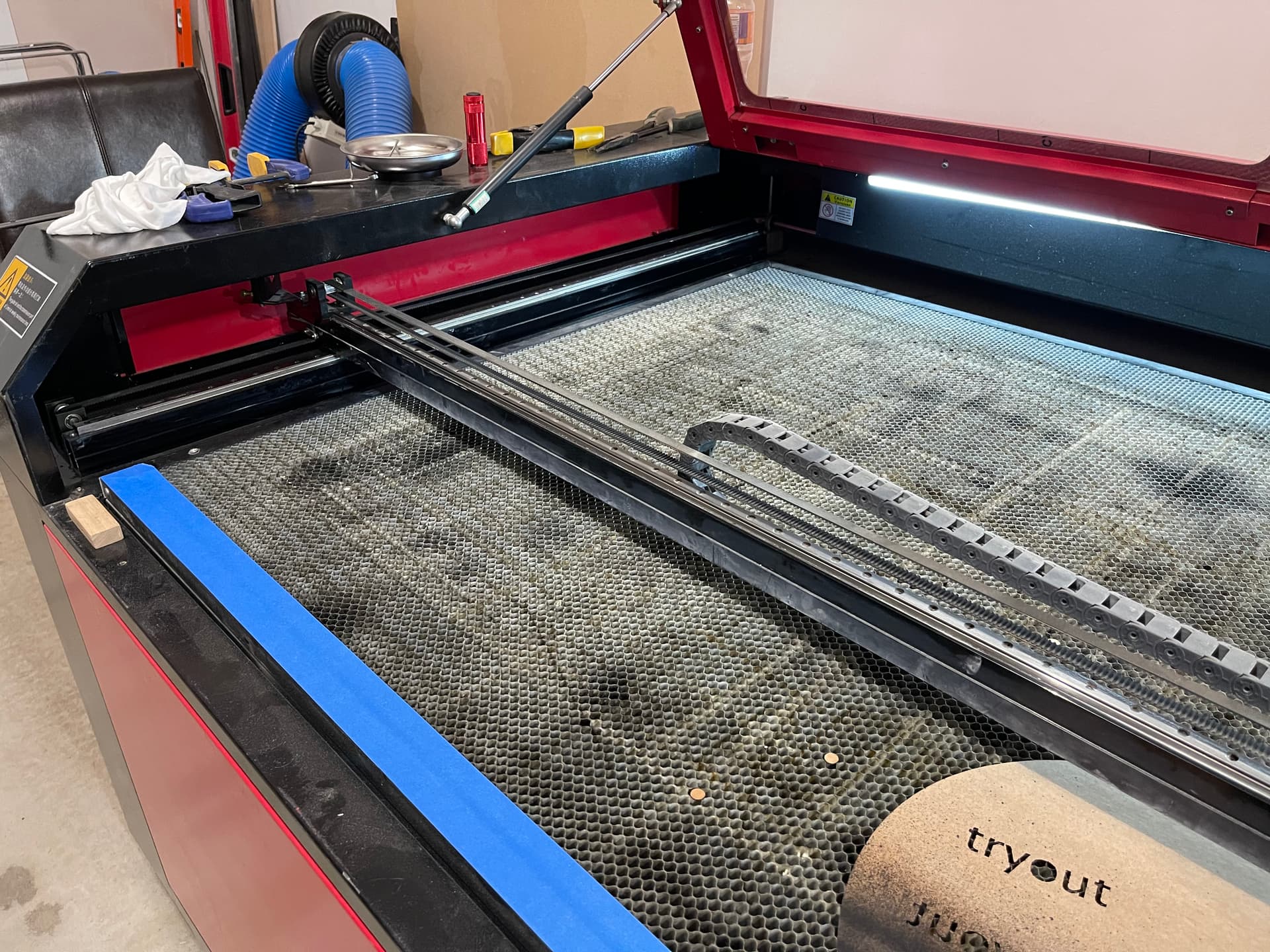
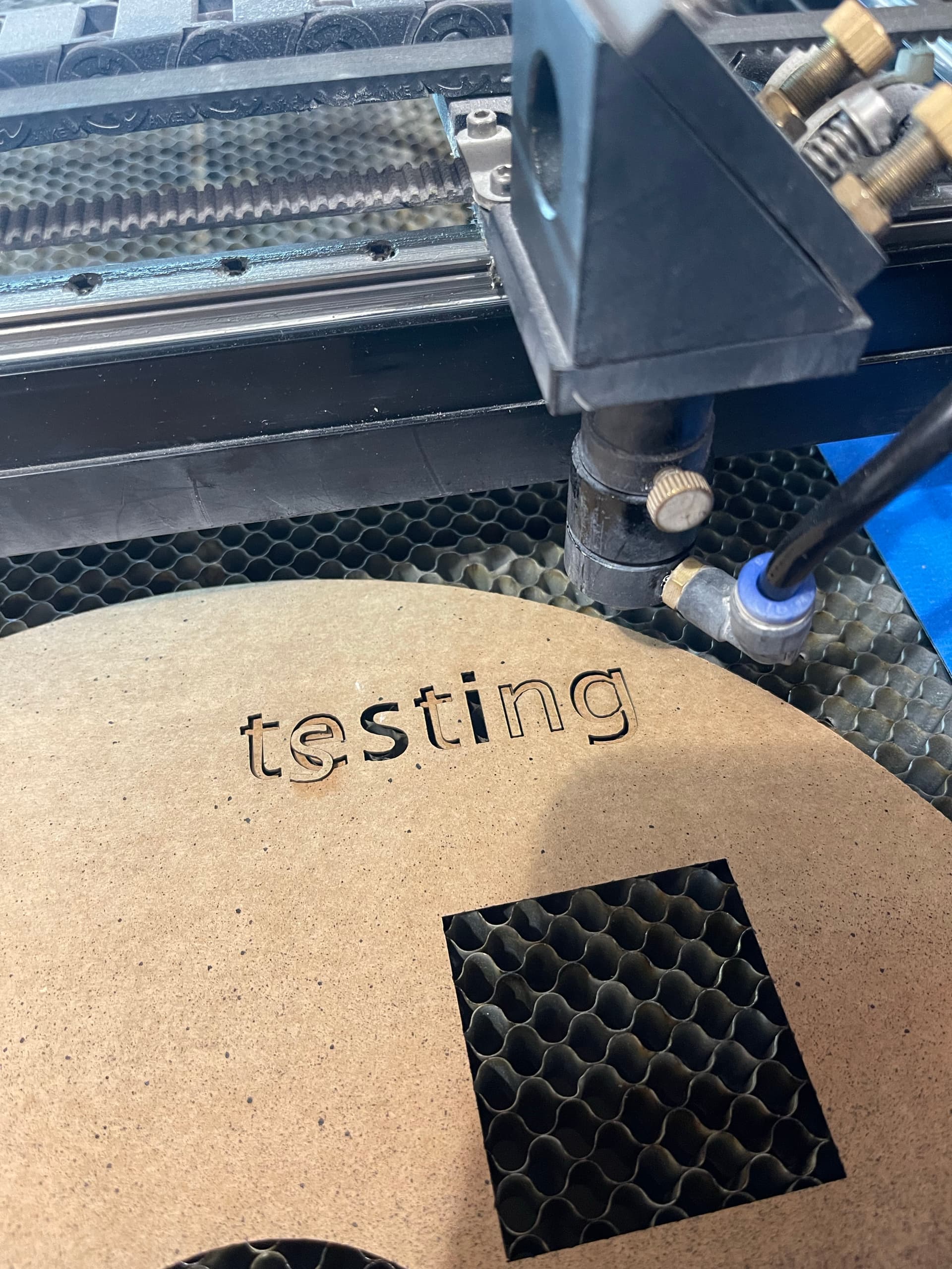
Please see the pictures for my explanation.
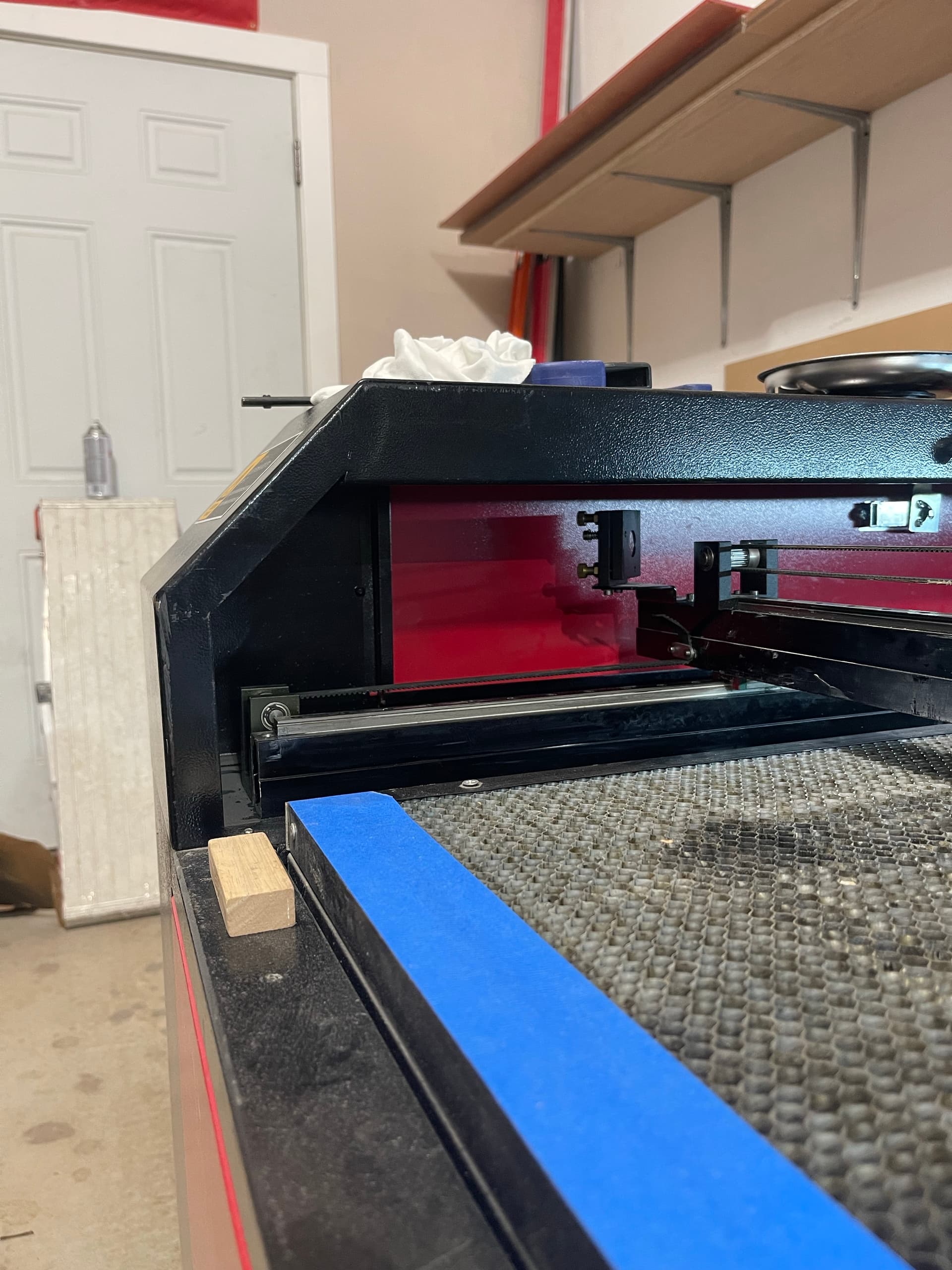
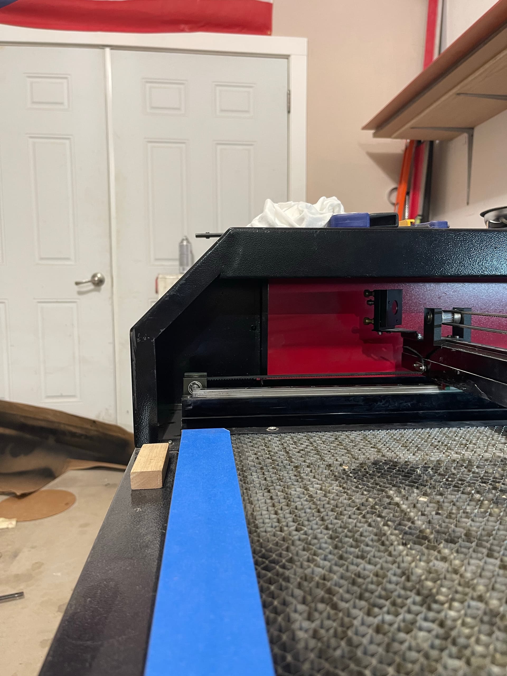
You see that angle there. If I move the gantry all the way towards the front of the machine that mirror will crash into it. The motor is on the opposite side and keeps going that causes the belt to skip a few teeth.
To answer the question of “Are you running without a ‘home’ on that axes?” Well you got me there!
I wouldn’t know how to look at this or for this.
My Machine runs on a Ruida controller and I use Lightburn as the software on windows 10.
If someone can chime in on how I look for this or can manage to fix this that would be incredible.
Sorry, for late replies, I was at work yesterday so I couldn’t take pictures of the laser to be able to reply.
The blue tape is now there as a “hey don’t go past this point or you will have to re align everything again”
Thanks
It’s clear you Ruida is not configured or running properly.
Ruida, and most other stepper motor type cnc machines must perform a ‘home’ operation when they boot. If they don’t/can’t they won’t know where they are. They are usable in this condition, but much more difficult to work with.
When you power it up, what does it do?
Does it run into anything on the boot.
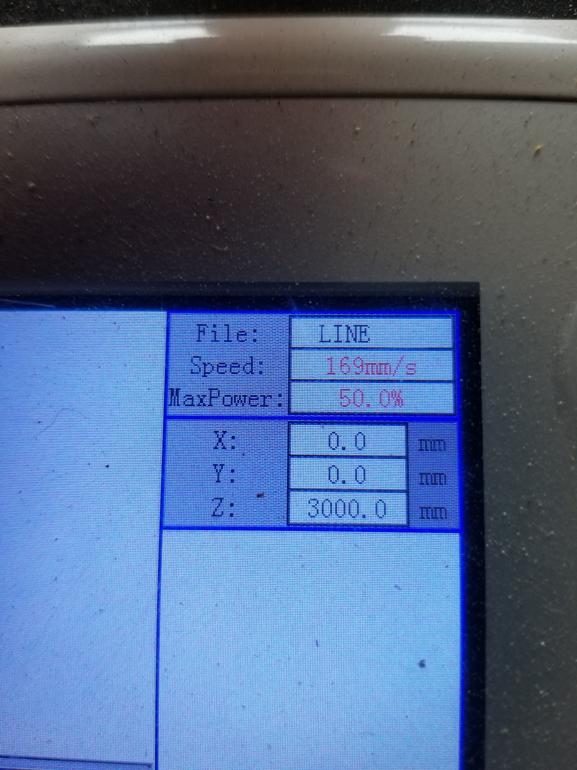
Examine the Ruida console display, what are the X, Y & Z coordinates.
What is the ‘Edit → Machine Settings → Vendor settings’ check these to ensure they are the right numbers for your ‘work area’…
My X & Y axes are bigger than most 5030 machines @ 508 x 342 as you can see
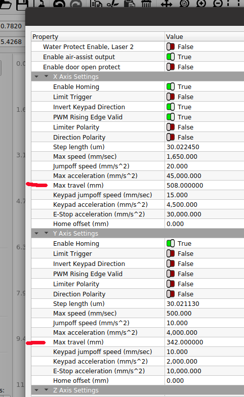
Since your Y axes seems to be the issue, check that one… However, I’d ensure both are correct to match your machine.
So…
Does it home and which corner. Check the console window to determine the X & Y coordinates
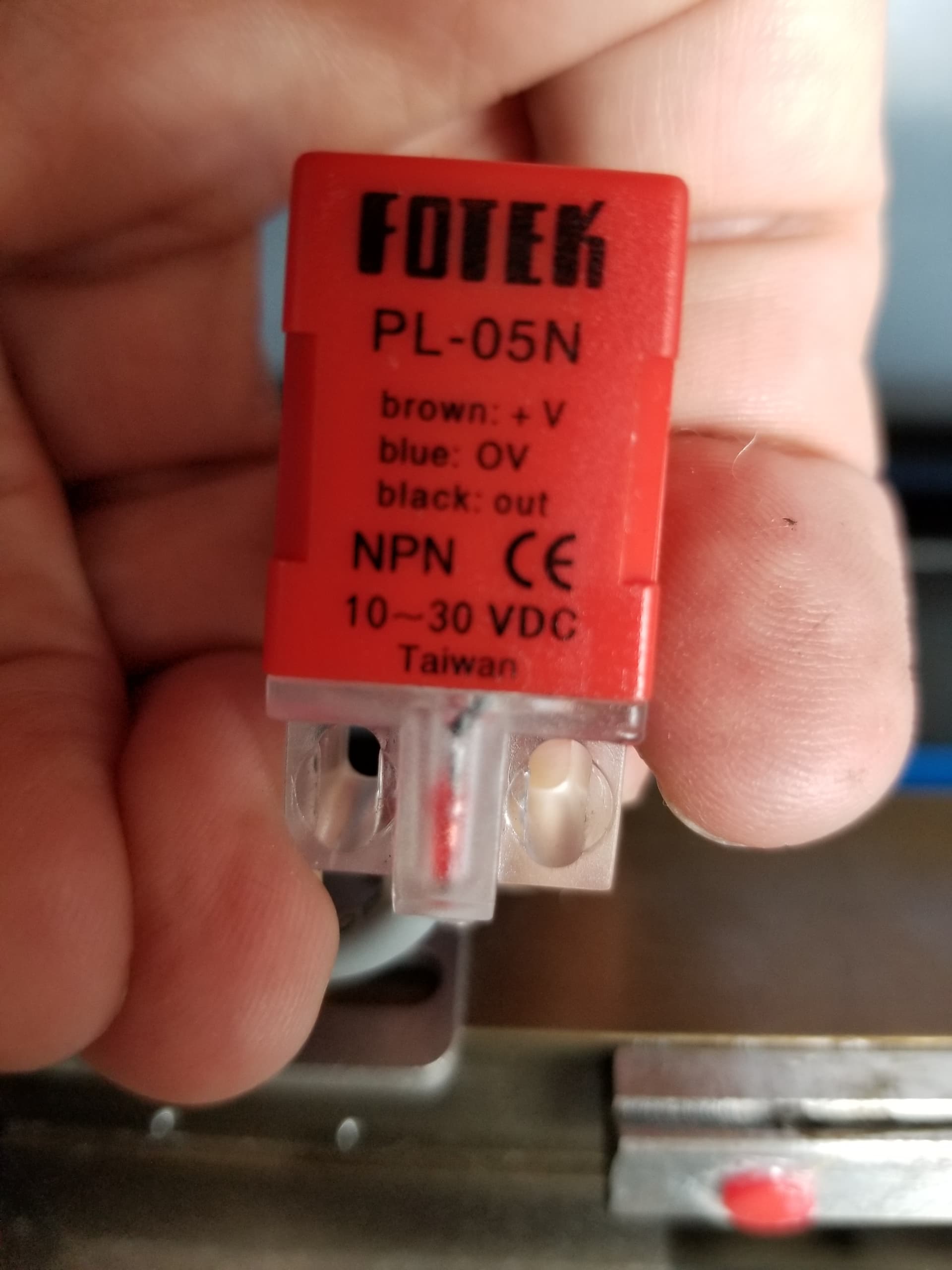
I know it’s on the right because I can see the limit switch on one of the photos… most likely the rear/right. The one I can’t see is probably back on the right hand side.
They look like this or similar.
I’m going to the doctors today, so won’t be back till late.
Good luck.
![]()
When I power up she homes to top(rear) right corner.
She does not run into anything.
“Examine the Ruida console display, what are the X, Y & Z coordinates.”
I do not know how to do this on the ruida console
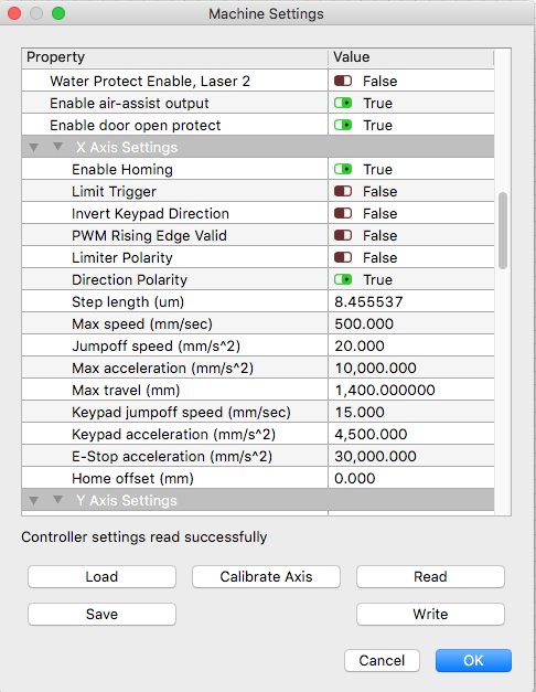
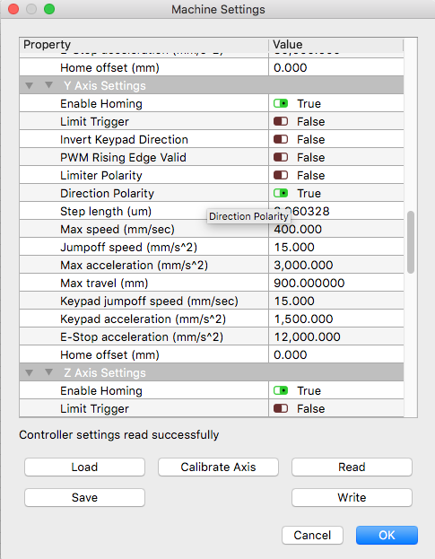
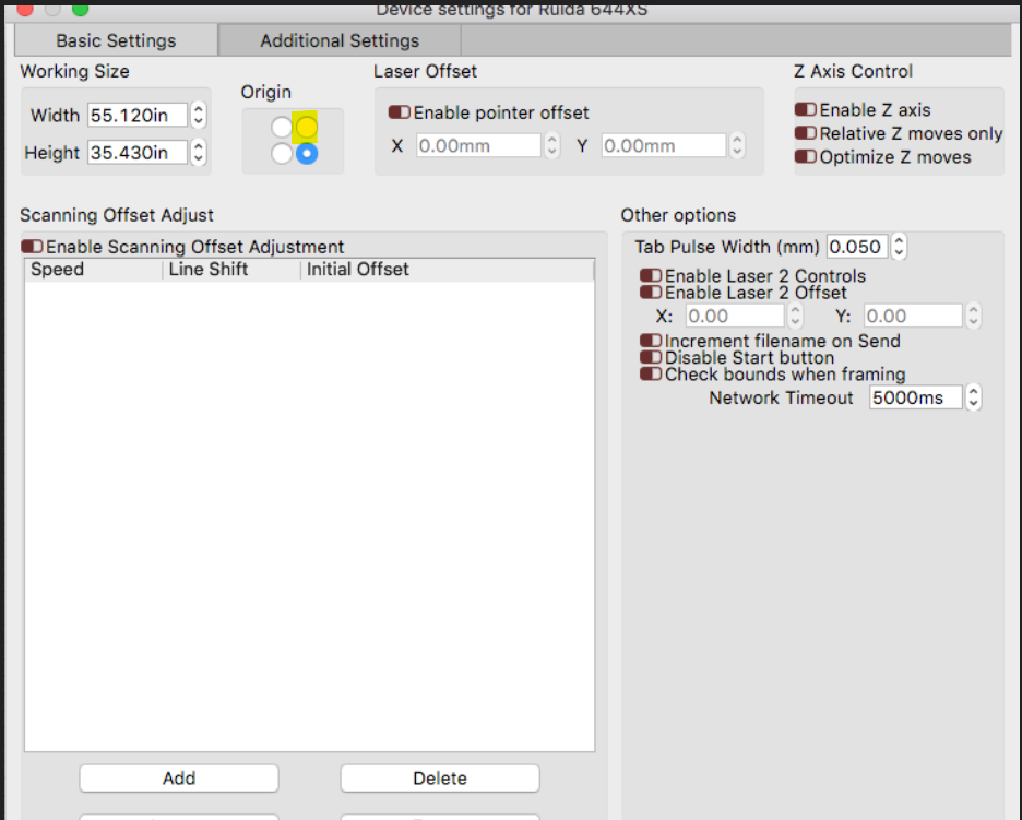
Please see pictures of the screenshots i took of my machine setting in lightburn
Thanks
If it’s homing ok then it’s probably OK…
The values look OK for your limits in the controller.
I was actually asking about the machine console after booting…
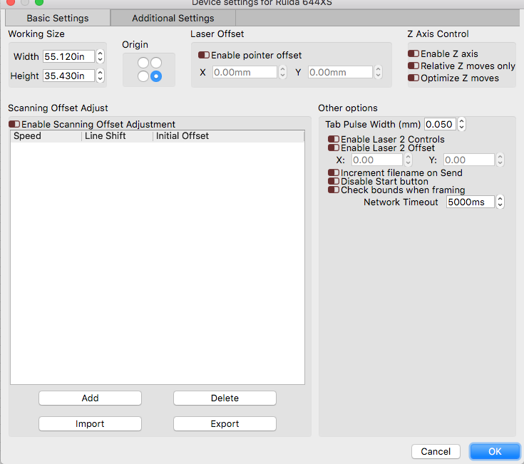
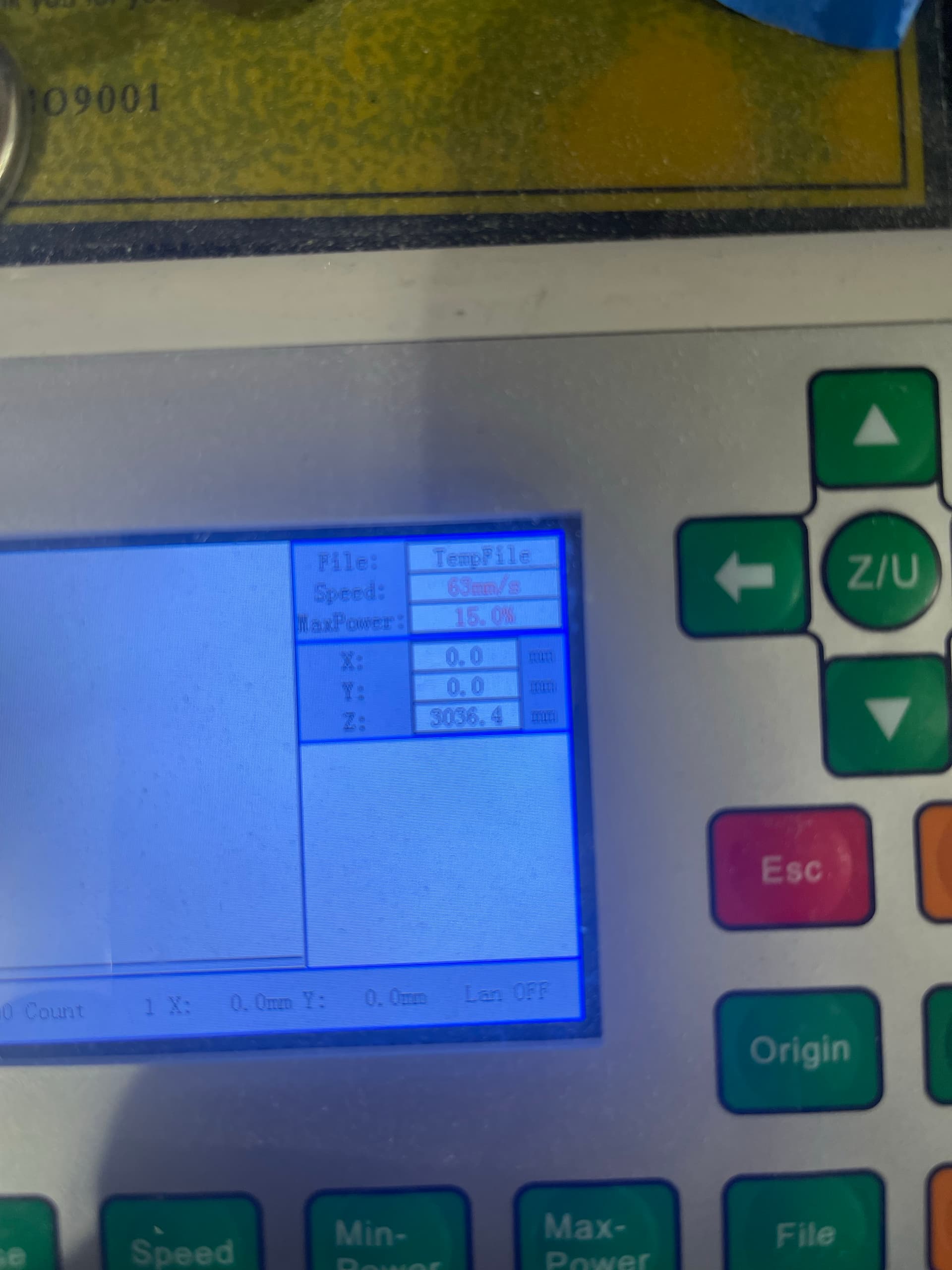
This is my console on the machine immediately after boot, or homing, with the X & Y set to zero. I don’t have a Z axes, so it will reflect the default for that axis, which is maximum value.
When you set these up, ‘Edit → Device Settings’, Basic Settings tab, ‘Origin’ should be the homing corner of the machine. This tells the software that the machines ‘home’ is in the front/right, which is not correct.
This identifies the home of the machine, and is not related to “what’s normal for you”, just how the machine is configured.
The results are that your image has to be mirrored somewhere or it would come out mirrored. If you look at my graphics about quadrants, it will mirror across the X axis.
If you want to change, to what you are used to, use ‘Job Origin’ in the laser window.
You must have something flipped to correct for that change of position. So if you correct it, it might need to be in two spots.
![]()
Yes things are mirrored and bugged me, but now I know why. TY. So how do I make it so that I can cut/Engrave as I see on lightburn
Here is a image of the console
To fix the mirroring change the origin position in Device Settings to top-right.
Keep in mind that this will mirror all your previous designs created with the old origin. In your case, this is actually probably what you want.
As far as the head crashing this shouldn’t have really affected that as max travel should still have protected you.
Try this. Once homed, use jogging controls to get as close to the danger boundary as you dare. Then check the position of the laser in Move window or control panel. If the Y value is less than 900 mm (35.43 in) then your bed is defined too large for your actual setup. Reduce the Max Travel on the Y-Axis machine setting to the actual max travel. You may want to back off a couple of mm for extra clearance. Make the corresponding change to Working Size in Device Settings. You may want to switch from inches to mm in the LB toolbar or settings before doing this so that you can ensure the values match exactly.
I suggest you take a backup of your machine settings before proceeding with any changes.
Under the Z/U options, there is a screen orientation. This will only effect what’s on the machines console display, but all of it should be working properly if the machine is configured correctly.
If you have problems with configuration, drop us a note…
We’ll get you and running.
@berainlb did you see how far his m2 hangs out in front of the gantry?
Good luck
![]()
Did this. Thank you
Also did this and now no mirroring needed, Such great help, really appreciate it!
Dont be jealous, lol
just kidding!
I just assumed @torturebori likes to live dangerously.