Seeking to verify rotary setup is correct

I’d like to ask those that are already using rotary with success to verify please that I have my new rotary setup adjusted and operating correctly. The setup appears to be producing a test pattern generally correct but with one exception, that the arc segments of a circle which run mostly perpendicular to the rotary axis are getting higher laser power than those arcs which are mostly parallel to the axis. I’m not sure if this is abnormal or if its as good as it gets.

If its as good as it gets (normal), then perhaps its explained in this post by Oz a couple of years ago, although he seems to imply the effect should not occur and that the speed corrections that LB produces would prevent it. The OP of that post mentions a “pause” that occurs during the cut which seems to account for the heavier burn, I’m not getting a pause yet I have the heavy burn.

Here are some files to help assess.


Note that the diagonal line is also heavy burn, which seems to be explained by the gcode as its speed is 707mm/min vs the layer speed of 1000 mm/min.

L- rotary test.nc.txt (5.2 KB)
L- rotary test.lbrn2 (9.8 KB)


Screenshot 2023-01-03 175740

Thanks for any help, or to just advise that ‘its normal’.

Might be nice to know what kind of machine you are running, as you seem to have more than one.


Looking at your photo, many of the lines are not consistent in burn and focus. Compare these two…

InkedIMG_1706


That must be some fast machine to do that engraving at 1000mm/s

:smile_cat:

It’s a diode so it’s per minute rather then the CO2 per second
:clinking_glasses:

The out of focus issue is the camera taking the picture, not the laser. The inconsistent laser burn is the issue I’m inquiring about in this post/thread. The machine I’m using is a MillRight Mega V XL, (and as @Sasquatch noted) mm/min feeds, its a diode laser, Neje A40640 dual diode 15W (output).

1 Like

I conducted more testing today and built a simplified test case to demonstrate the incorrect feedrate on linear / angular combo lines and shapes, basically any rotary cuts/etching other than parallel or perpendicular to rotation. I’ve submitted the info to LB support but no word yet.

Since this is my first venture into rotary work, it could still be a setup issue, will wait to hear from LB. However, I was able to modify the feedrates on a LB gcode file which then does demonstrate consistent angular line burns, so that seems to suggest my setup and config is right.

1 Like

Maybe correct … might be possible to have a bad setup and fix the ‘configuration’ error in the gcode…

Good you sent it to support… I’ll be hoping you will let us know what they say.

I don’t know how many of those machines are around this group… All of these work generally the same, but every machine seems to have it’s own idiosyncrasies. Especially controllers.

Good luck

:smile_cat:

Here’s an update on the problem which as noted on Jan 4 post is an incorrect feedrate on linear and angular G1 moves/cuts.
After 3 days of testing, debug, and study I have found that…

  1. the problem only manifests itself on XYA (optionally Z) CNC machines, where A is a dedicated rotary axis with it’s own driver and motor. Even simpler, only on XA combination G1 moves, which are typical in dedicated rotary gcode. So if you have an XY machine where Y axis motor drive is shared with the rotary axis motor, then you won’t or shouldn’t experience this problem. I ran a test to prove this after temporarily re-configuring my rotary to use XY motor control. However, I can’t continue to run this way because my Y motor driver is voltage/current tuned to driving 2 motors not 1, so it will burn out my single rotary motor if I do this for any amount of time.

  2. Given this XA setup to trigger the problem, even if you have an XYA[Z] machine, if you only use 0 or 90 degree scan during Fill Mode when cutting/etching shapes, then you won’t experience this problem. 0 degrees being parallel to the rotary axis and 90 being perpendicular to it. I ran a test to prove this.

  3. On an XYA[Z] machine, if you scan (Fill Mode) at other than 0 or 90 degrees, or if you use any mode other than Fill Mode, then you will experience the problem unless your design is simply 0 and 90 degree lines. I ran a test to prove this.

The problem is due to the grbl X and A axes using different units of measure, which carry forward into motion (feedrate) interpretation. X uses distance/time feedrate, A uses degrees/time. When performing this combo axis move in G94 grbl Distance Time mode, which is the normal motion mode in XYZ coord system, the vector in both axes must share a common feedrate as there is only one F value in the G1 statement block. 1000 mm/min does not equal 1000 deg/min unless the circumference of the cylinder is exactly 360mm, or 1mm/1deg. In my case the cylinder is 267mm circumference. So the math being done in this case to figure out the common feedrate of both axes where the laser is moving at the desired 1000mm/min appears to be wrong, again unless I have a gross misunderstanding of this problem.

So to prove that this is the problem here, and that my machine is configured correctly, I modified LB gcode to use G93 Inverse Time motion mode for those statements that are G1 XA combo coords, aka linear and angular moves. That test and subsequent laser cut work perfectly.

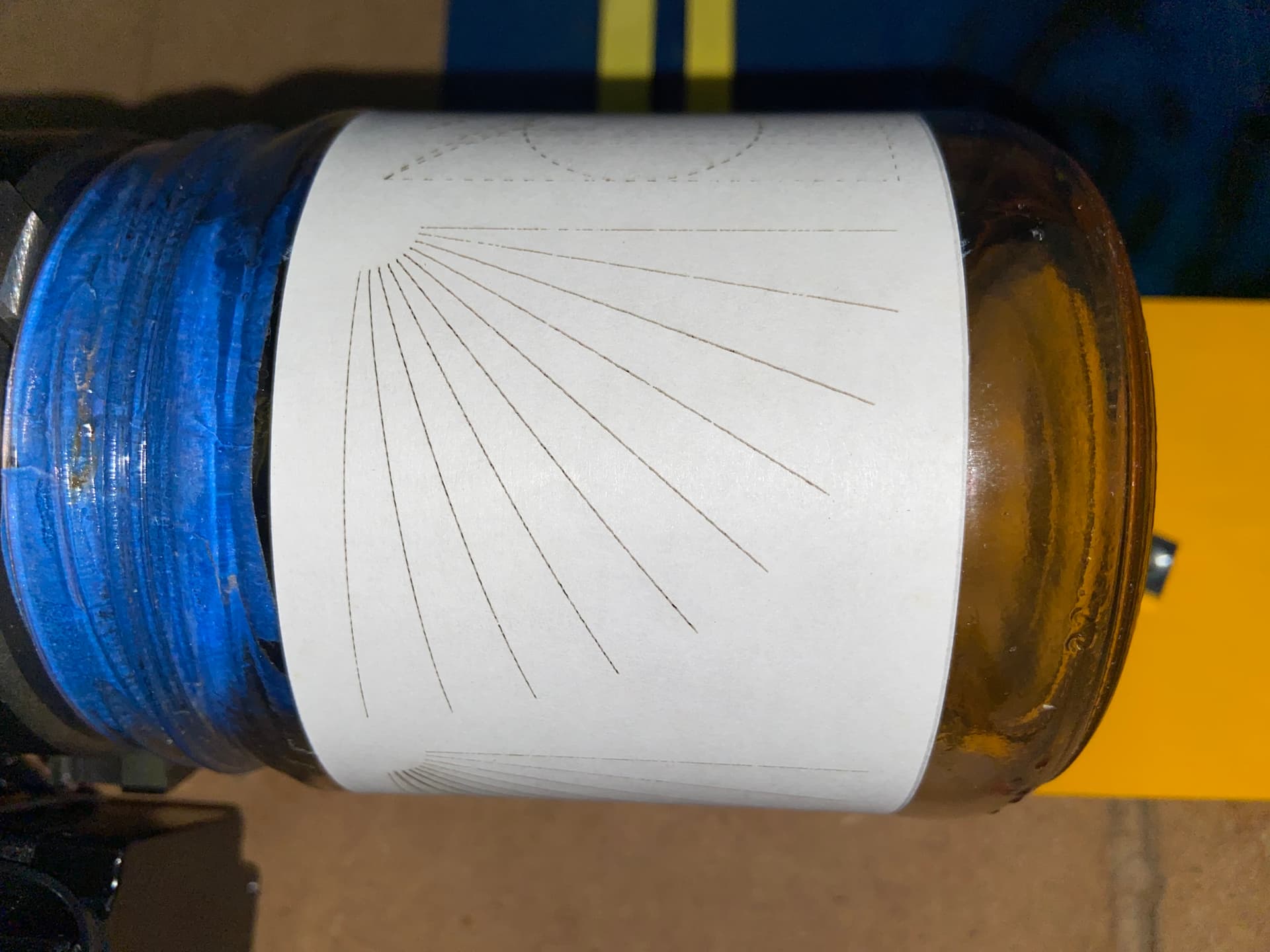
Although LB support has been in contact with me twice in the past 3 days, it’s always at midnight when they write me, and it seems like the problem has not left the ‘user error’ screener yet. So I’m including all the files in this post. I suspect LB support would really like to know if someone else with a dedicated XA rotary setup will experience the same problem. When I run the tests I use a glass mayo jar as a cylinder and wrap/tape a piece of 20# white paper around it. I’m also using a chuck on the rotary, I’m not sure if the problem will manifest on a roller device as there are additional calcs used I suspect. And lastly, I use Mirrored Output to Rotary mode but LB gcode without that mode shows the feedrates are identical.

Thanks for any help one can provide in advancing a solution here.

cheers,
Lou
XA tcB.lbrn2 (35.1 KB)
XY tcB rotary.nc.txt (600 Bytes)
XA tcB G93.nc.txt (756 Bytes)
XA tcB.nc.txt (662 Bytes)
XA tcB G93 v G94 compare rpt.html.txt (11.6 KB)


winner winner chicken dinner :slight_smile: I’m out of user error jail screening…
LB Support wrote me minutes ago with good news, progress…

“Hi Lou, Your issue has been replicated here in versions 1.3.01 and 1.2.04 and this ticket has been escalated to the development team. Again, thankyou for your patience at this time, we appreciate your time and input into this. I believe you are correct in that there are not as many people using A-axis, and less again using it with line mode…”

Persistence pays off!

So in the meantime of waiting for a fix, I can’t sit still, so yesterday I ran yet another test whereby I use the correctly calculated G94 mode feedrate for each G1 XA move in my “XA tcB.nc” test case and it proves to also resolve the problem. It worked as expected, just like the G93 solution and photo. This means the solution should be, hopefully, a simple math fix in the LB code that calcs the feedrate in these G1 XA move statement blocks.

Although I doubt they need this, I shared it with LB support yesterday as well, and a reply email indicates there is still some doubt on their part as to the issue being a valid LB bug or not, meaning he mentions speculation that the problem is with my CNC grbl firmware not behaving normal. But everything I’ve read on this linear-angular move topic, including @LightBurn own forum post from Jul '20 that I note at the top of this thread, says otherwise; that my machine is doing exactly what its being coded to do, move a G1 XA coord at the Feedrate interpreted by the linear axis, and synchronize the angular axis feedrate to a speed where both axes meet simultaneously at the XA coord, as specified in distance (mm this case) and degrees. And all the testing I’ve done has borne out the same conclusion, because when the G94 or G93 feedrate is right, the move works perfectly.

LB is currently using only the calculated X axis feedrate (XF) in mm/m which moves delta X (dX)mm in the time t that it takes to run the hypotenuse of dXmm,dAmm (after calculating dAmm of course, since A is coded in degrees). What’s missing is consideration of the feedrate vector component of the dA axis move distance in degrees. So do the same A axis calc to determine A axis feedrate (AF) using the same dXmm,dAmm time t, leaving the result AF in deg/mm. With these two disparate feedrates, one can now calc the correct G94 feedrate to use on each G1 XA gcode statement, which is the hypotenuse vector of feedrates XF and AF, its ok that they are different units at this point, (in essence they are not different, they are now ‘feedrate’ units for this XA move statement only, and only one feedrate value can be equal for both A and X axes, for this specific XA move statement only). The deg-to-mm, circumference, and desired cutting feedrate considerations have all already been taken into account at this point when time t was calculated as the time (minute units in this case) to cut the hypotenuse (in mm) of this specific dXmm,dAmm at the desired (designed) cutting feedrate.

So the formula for a G94 mode and common XA axes feedrate is: F = sqroot(AF^2 + XF^2), where AF and XF are the feedrates in their respective units/min for each axis to move its respective right angle leg in equal time t to cut the dX,dA hypotenuse line segment at the cutting feedrate in the LB shape layer, 1000mm/min in my test case. This formula also accounts for either AF or XF being zero, which is 0 or 90 deg respectively to the axis of rotation. Of course, repeat/recalc for each G1 XA Line segment or Fill segment or arc chord that is to be coded.

Here is a report comparing the gcode files “XA tcB.nc” which is produced by LB untouched, and “XA tcB G94 corrected.nc”, which I modified only the Feedrate component of each G1 XA line. You can easily see the degree of error in the LB feedrate as the line angle increases 10 degrees in each case from 10 to 80 degrees as shown in the previous post photo with red arrow. The 80 degree line has the greatest degree of over burn and the slowest feedrate, so that stands to reason why its over burnt.


XA tcB G94 corrected feedrate compare.html.txt (9.3 KB)
rotary lin+ang combo feedrate calc V3.xlsx.txt (34.2 KB)

Here’s an update on this mess I’ve created and an attempt to clear it up…

Primarily the problem (in my machine’s case) continues to be the problem as described in this post #8 above

My machine mfg (MillRight) folks have been looking at this in priority with other work for the past week as a possible bug in their custom grbl v1.1i. The history of them even having a custom grbl version has origins in that they were one of the first Arduino grbl versions to support XYZA axes, having adding dedicated A axis support in the then grbl XYZ v1.1i in 2018-2019. Although we’ve corresponded several times in the past week, and I’ve run some further testing for them where the results suggest its their bug in grbl (according to CNC Machine Overview) I have not heard from them that they have actually run my simple “XA tcB.nc” test case that produces the over cooked laser lines in the photo of post #8. However, I corresponded with another of their customers that has the same model of machine as I do, and he’s a known prolific rotary project craftsman, he tells me he has noticed at times much slower than expected G1 XA moves but couldn’t put his finger on the cause; he’ll run my test case within a day or so to confirm it and get back to me, as will the mfg I expect.

So net msg is-

  1. I have two more data points that suggest the root cause bug is in the mfg’s custom grbl controller of my machine. Absolute confirmation of this will take another couple of days perhaps, until someone else with my machine model runs the “XA tcB.nc” test case and times the G1 XA moves, those are all 45mm lines that should traverse in ~2.7secs if grbl is operating normal, in my machine’s case the steeper angle lines take progressively longer times to traverse, the last line at 80 deg takes ~15secs; hence the cooked line.
  2. However, in another test case I made the other day for LB support to demonstrate the problem, I discovered that LB ‘Fill’ mode uses the layer design feedrate for F value on all scan angles 0 to 90. So any angle other than 0 degrees is using the wrong gcode F value, but as the angle gets steeper in this case, for a normal operating grbl, traversing the lines gets faster since delta X is getting shorter and the programmed feedrate is not changing for those G1 XA moves. This threw me for a loop early on in this saga and I went down the simple test case rat hole of “XA tcB”, and being “lasered” in on that expecting it was the cause for all oddities in feedrate that I observed in the gcode and as my machine ran the motions.

Net net - It appears very likely there are two bugs here, one in my machine’s grbl controller, and one in LB in the case of Fill at other than 0 deg scan angles.

Both companies are working on it at a priority relative to other issues, understandable.
Here is the holy grail of both bugs in one test case.

Cheers,
Lou


XA tcC Fill-OffsetFill-Line.nc.txt (8.3 KB)
XA tcC Fill-OffsetFill-Line.lbrn2 (26.2 KB)

Emailed you a link to try.

@LightBurn , thank you for a quick fix.
Upon trying the fix, it occurred to me after I gen my “XA tcC Fill-OffsetFill-Line” test case that I can’t run it on my CNC for 2 reasons

  1. my CNC is reconfigured to use XY rotary right now and jobs in the queue.
  2. when I reconfig to XA, I still have the bug in grbl, so each line would traverse unbearably sloooow.

I looked at the gcode and see the distinct pattern of lower F values for shorter X and greater A deltas, so it appears to be right. But to be sure, perhaps someone on this forum with an A axis and a none grbl controller can test this for time being and foreseeable future, I don’t know when MR-grbl will be fixed.

I can modify the test case to drop the OffsetFill and shape [out]Lines to avoid all the small XA moves, and rather just run a few scan lines of a small LPI Fill just to know if the laser point movement looks correct; but the speed will be wrong on my machine so I have no way to verify if the fixed F values are correct. I’ll be able to do that tomorrow.

For those following this saga, the related bug in MR-grbl has also been verified to exist in grblHAL, and it’s being fixed now. MR-grbl and grblHAL share a common fork from a few years ago, so it’s possible if not likely that other grbl variants/forks that can control 4 axes have this same G94 G1 XA feedrate interpretation bug, see the prior post here for those details.

Cheers,
Lou

@LightBurn I generated a variant of the XA tcC Fill… test case to just contain Fill shapes at numerous scan angles near 0, 90, and 45 degrees. Since I can’t run the test case on my CNC due to the grbl bug, I imported the gcode in xls, parsed it, did the math to calc the feedrate based on Xt and length of XA scan line (each line), and found the xls calculated feedrate matched exactly to your LB calculated feedrate. That’s the best test I can think to do for now under the circumstances.
XA tcC Fill-OffsetFill-Line wfix.lbrn2 (102.5 KB)
rotary lin+ang combo feedrate calc V5.xlsx.txt (276.9 KB)

related… No news from MillRight on the MR-grbl fix.
But Good news from grblHAL on their fix, it should be ready to test later this week I’m told. It will likely be a compile time option of grblHAL until the fix is vetted by several XYZA capable users. I have ordered one of the many grblHAL hardware boards and Teensy 4.1 which runs it, so perhaps in a few weeks I will have my MR-grbl controller swapped out for the grblHAL unit.

Cheers,
Lou

1 Like

The MR-grbl bug has been fixed. I verified both the LB fix and the MR-grbl fix on my MillRight CNC Mega V XL this morning. I have not yet verified the grblHAL fix; I will need to replace the controller on my CNC to a grblHAL board in order to do this, a task not likely to happen soon. grblHAL is interesting to me though in that it has several improvements under development for plasma process, such as a built-in grbl managed Torch Height Control (THC) and grbl manage Z anti-dive. However, my external THC in use now is working fine with MR-grbl and a Z anti-dive circuit when cornering, so there is no urgency to change things up right now.

Cheers,
Lou

This topic was automatically closed 30 days after the last reply. New replies are no longer allowed.