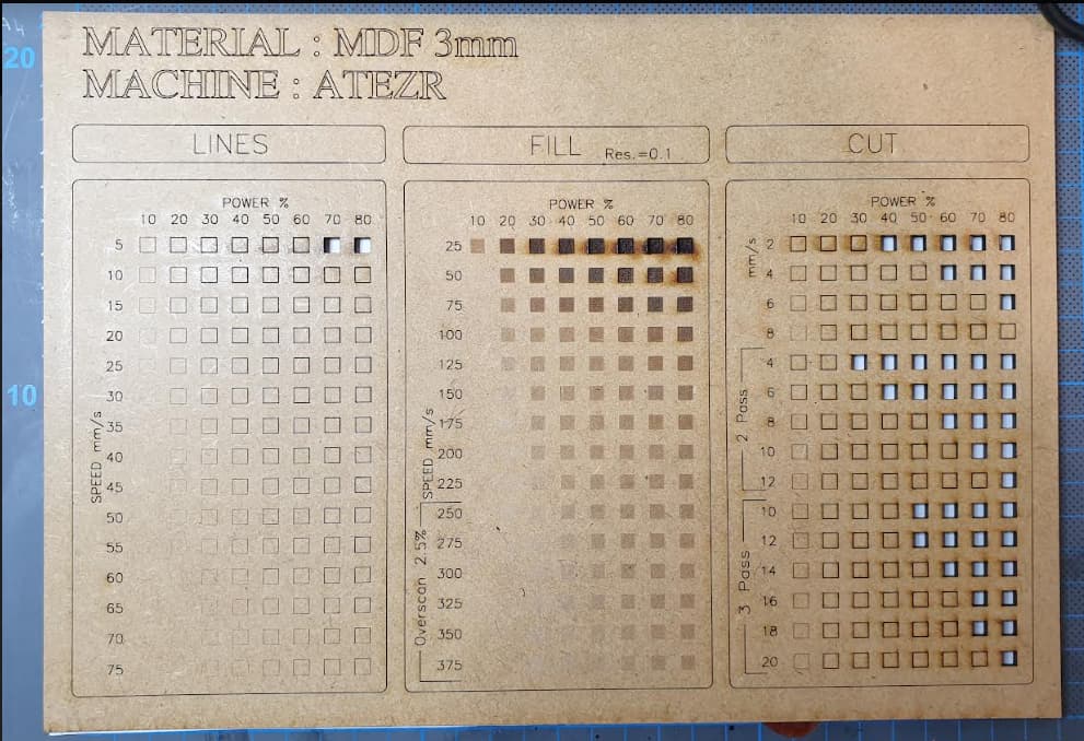
I wanted to share the gradient charts i’ve created, because i find them extremely useful. They are set to be done on an A4-sized material (297x210mm) but you can of course resize them as you wish.
You will find all charts in Lightburn format herebelow.
Speed and Power values should be ok with most of the recent machines, like X-tool, Atezr, CO2…
As you will see, there are 3 charts + 1 extra.
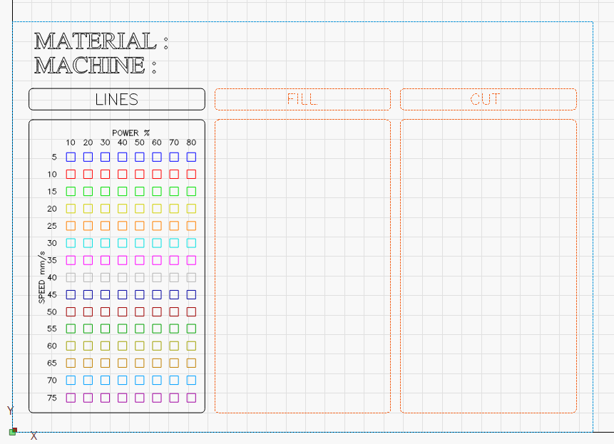
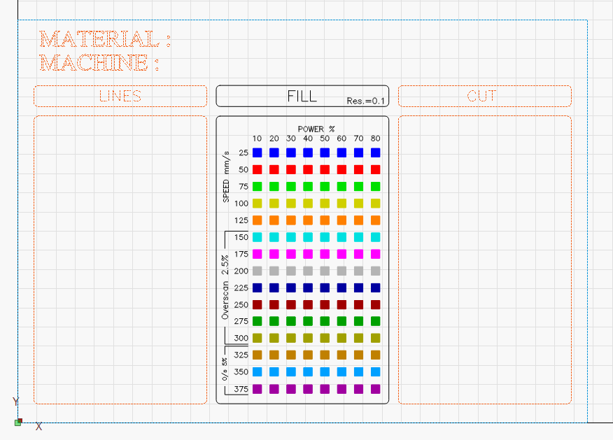
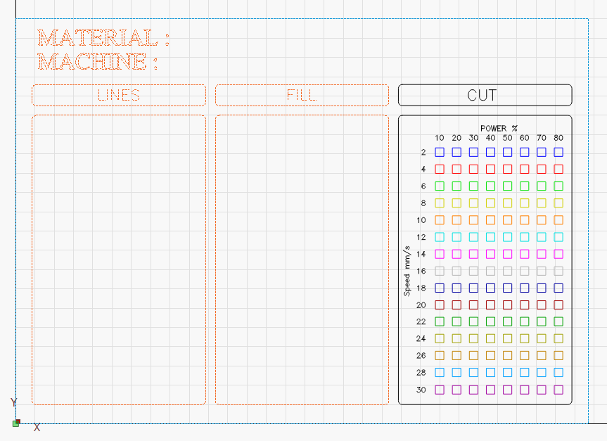
The first is for the line engraving, second for filled engraving, and third for plain cutting.
The extra is also for cutting, but includes portions with two and three passes.
How to use : simply load and run one chart at a time, leaving your material in place until you’re done.
Load the 1st chart, adapt as needed, and run the job.
No chart goes above 80% power. This is to save laser’s lifespan.
I’ve set up the charts in mm/s because i use both a Gweicke Cloud CO2 laser and an Atezr P20+ diode laser (which can reach utpo 400mm/s). If you prefer them to be in mm/min, just change this in Lightburn’s Options ; calculations should be done automatically for every layers.
For the CUT chart, i made two : one is with a single pass from start to finish, and the second one includes portions with 2 and 3 passes (as per the above exemple, the MDF picture). This can be useful for thicker materials.
I hope you will find these useful
If you do, feel free to offer me a coffee : www.paypal.me/xenoworks
These are awesome! I’m adding them to my bag of tricks. Thanks for sharing.
Also, zipped the four files into one file for easier downloading now that we know what they are.
(The usual remove the .txt from the filename for this forum applies here)
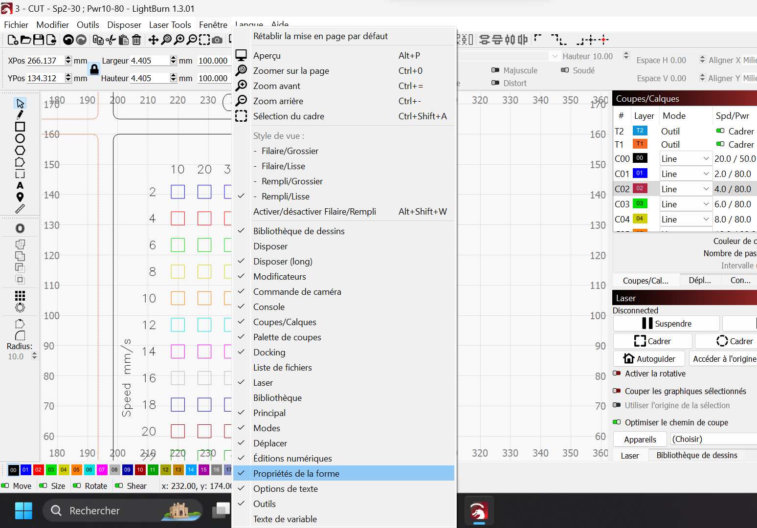
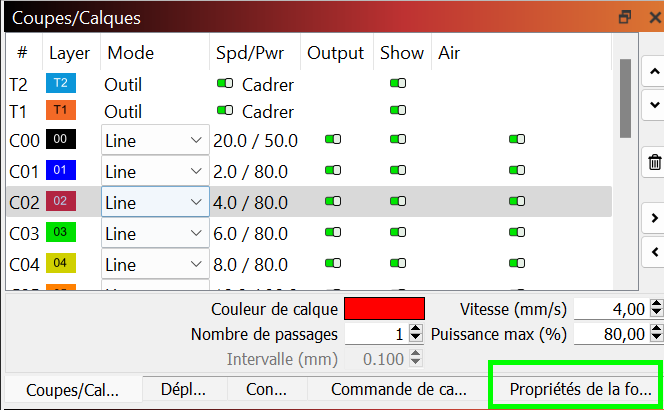
You then get acces to the Shape Property tab just below your layers, on the right side :
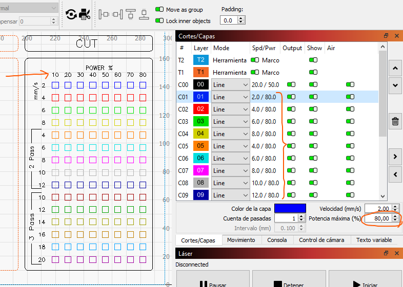
Now ungroup everything, select any square of any layer, and see in the “Shape Property” tab : there, it will show you the power this square will be burnt at.
All squares from left to right are from 10 to 80%.
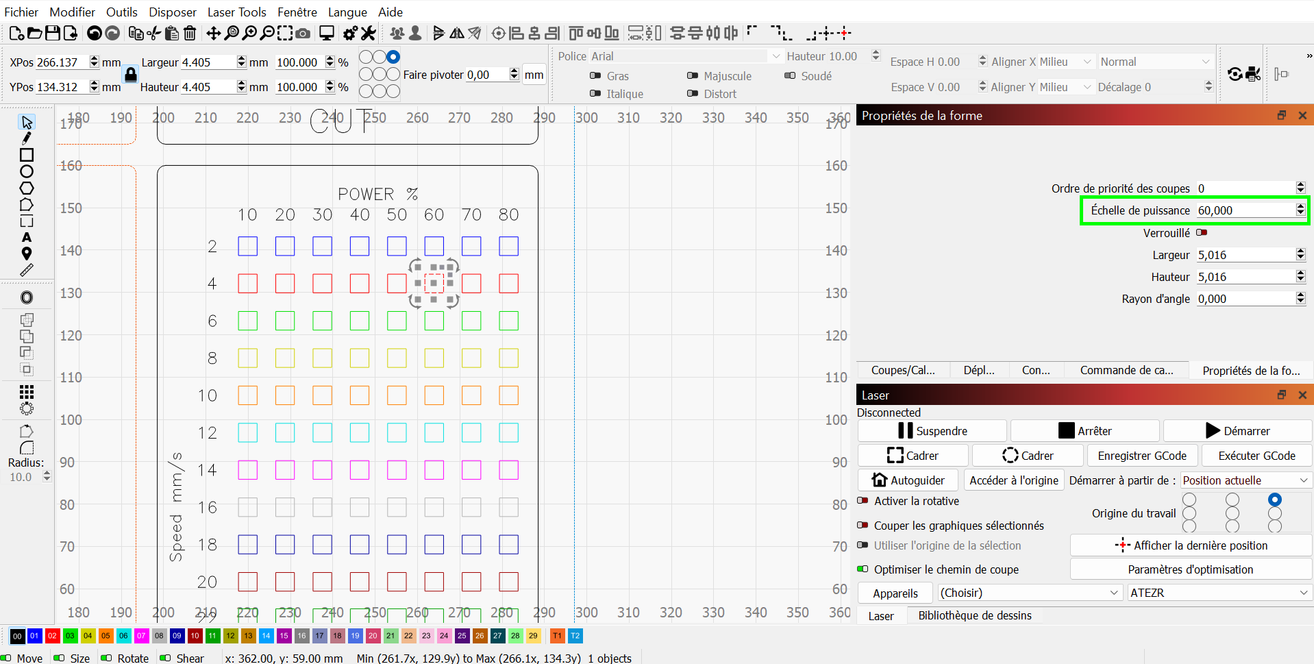
For exemple, if i clik on the red 60%, here’s what it says under Shape Properties :
Perhaps I don’t understand, but doesn’t power scale use a percentage of the shape’s assigned layer’s power to calculate the resulting output power? So, power scale @ 60% on a shape assigned to a layer with 80% = 48% output.
I’ve done number of my own test grids using the same techniques and always set the layer power to 100% so the power scale calc is easy. 13.5% power scale of 100% layer = 13.5% output… Am I thinking wrong?
I didn’t know about this, but it makes perfect sense. Thank you so much for putting this to my attention as it does changes things a little
Right, so i’ve corrected the files so that it now gives the real output, by setting the Layers’ max output values to 100% instead of 80%.
However, I did not add any column (90%, 100% pwr) because i wish preserve the module’s lifespan as much as possible.
I’ve also modified the FILL’s layers’ resolution to 0.075mm (about 338DPI)
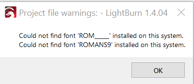
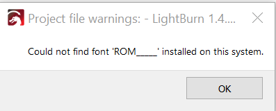
I’m getting the warning that there’s a font file missing on my PC.
I know that LightBurn will attempt to replace it with another if it can.
However, it would be nice to know what the font file is for certain or where to locate it. Maybe you could post it here?
Thanks for the files!!!
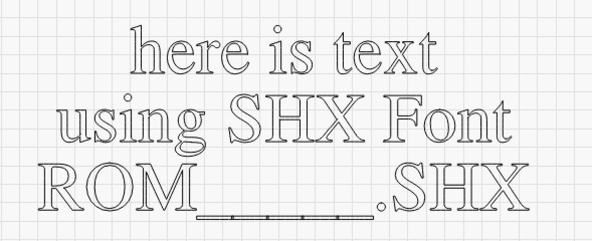
I created a small folder and placed the ROMANS9.SHX file in that folder.
That was to keep the number of selectable fonts to a minimum.
I have the big folder of 762 SHX fonts but certainly didn’t want that many available at the same time.