I have a K40 that has been slightly modified, I ditched the stock board and replaced it with an Arduino Uno and a CNC shield running GRBL. Lightburn works really well with this combination. No, this did not start after the Arduino Uno was introduced, the machine does have a lot of hours on it and that is one of the reasons I am leaning toward the hardware.
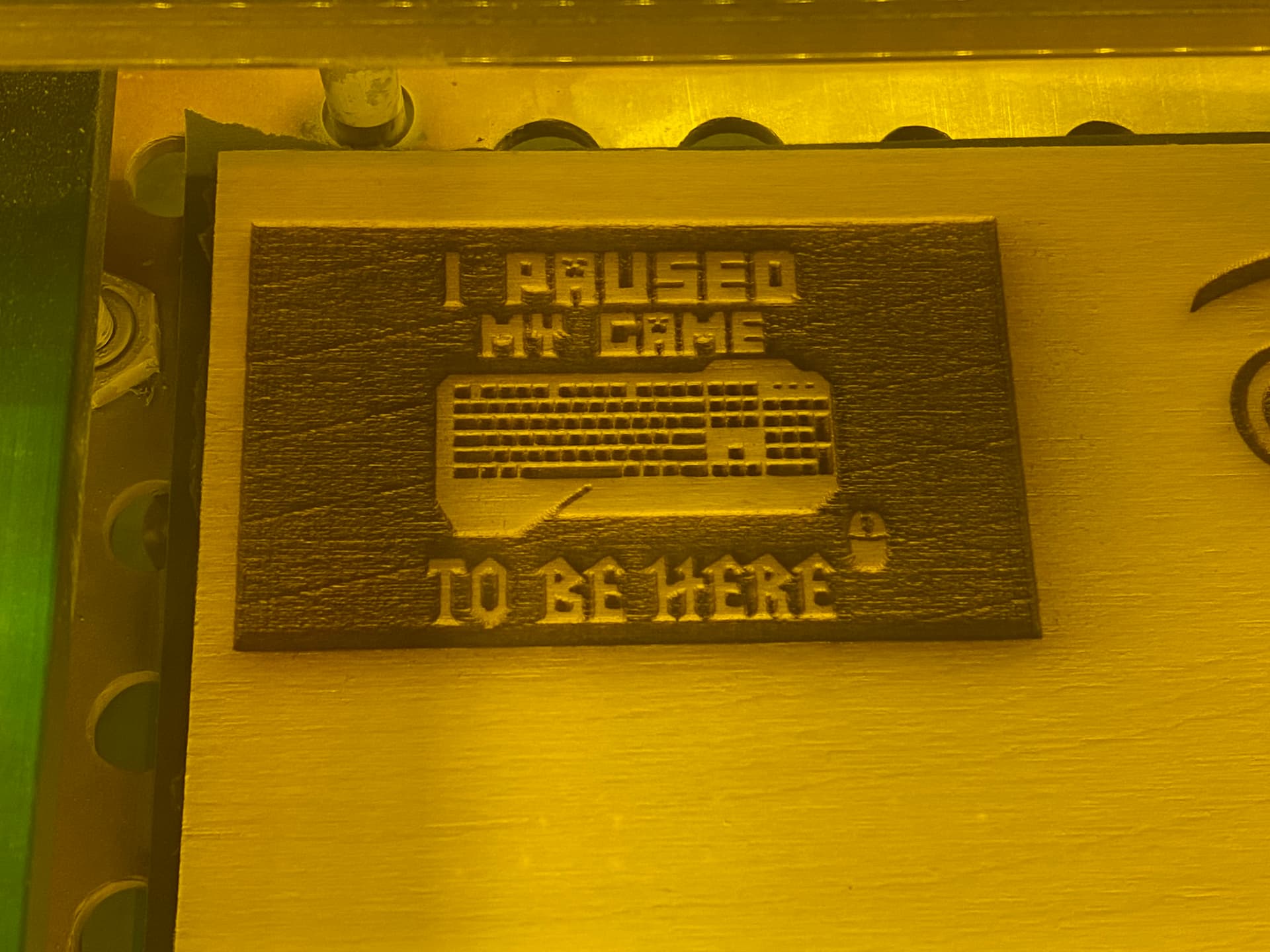
This file was burned at 100 mm/s at 30% power. There in another thread here that seems similar, but I am not burning an image so no dithering and no passthrough options to adjust. In that thread @LightBurn says
an interaction between the PWM rate limit in GRBL and the speed you’re running the job, possibly
Im not sure that is what is going on… Ill attempt adjusting the speed and see if that changes the output. In the mean time it would be interesting to hear everyones thoughts
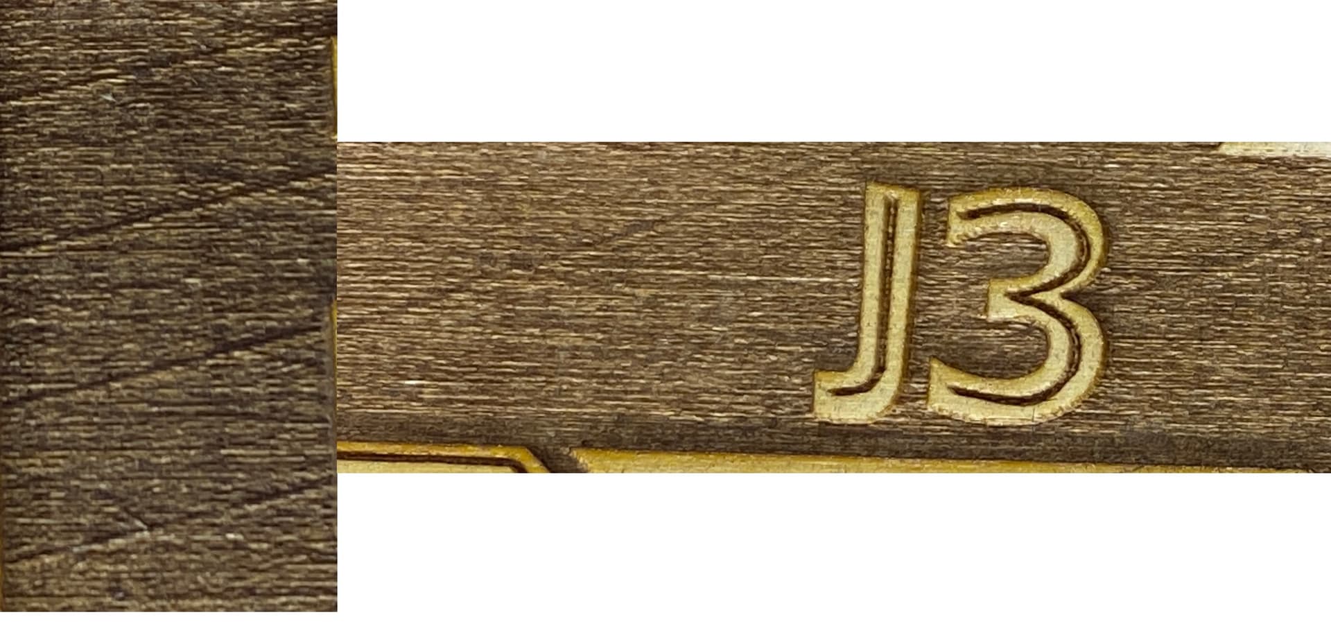
I ran a text that changed the power from 30% to 27%. It looks like the pattern got less frequent. The burn with the “J3” text is at 27% power and you can see the lines are further apart than the lines on the other burn. What is the solution to this? Is something not grounded properly?
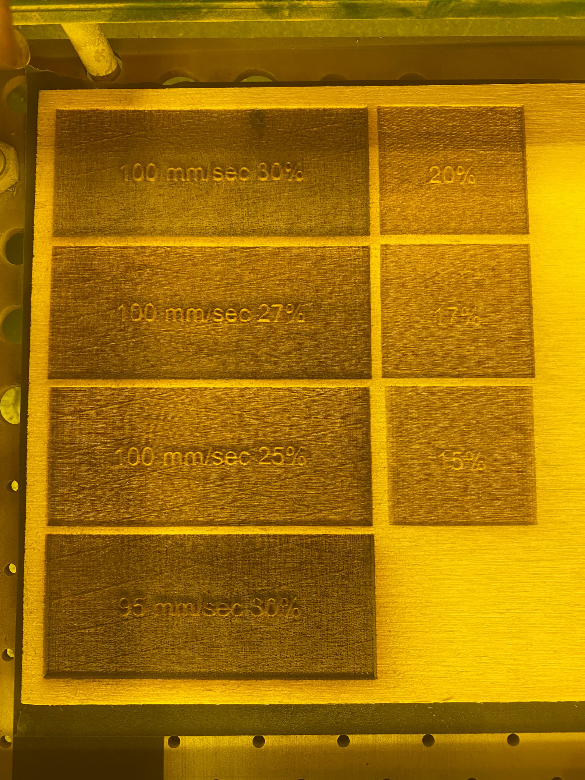
Without turning the wood, it is very clear to me that this pattern is not part of the wood layers. Looking at the 100mm/sec 27% and 100 mm/sec 25%, you can see that the patterns has gotten a little bit wider or further apart. Also, the lines are not aligned. I found changing the speed didn’t effect the pattern so the boxes on the left only adjust the power. and you can see the pattern in the 20% box has become very faint and even wider almost to the point where you can’t notice it.
This test has also made me realize that when I setup the Arduino board I did so to be able to control the power on the fly, whereas the Moshi board that comes with the K40 does not have the capability to adjust the power via PWM.
When I setup the Arduino it was during a rush, so I didn’t have the time to tune power settings. Right now 30% power is really 100% power (or at least its pushing the mA value to a point that I would consider it to be 100%). Is there a guide to adjusting this to be scaled appropriately. I’m fairly sure GRBL setting $30 is the max spindle speed.
Now that pattern I get on my 60 watt OMTECH. I generally don’t care too much but I am going to change the scan angle 90 degrees so the rapid scan is the Y axis. reason is the Y axis does not use pitched timing belt but rather a drive shaft. I was always curious if this was due to belt pitch issues or stepper motor resolution since it is a regular and repeating pattern. Changing scan angle should let me see…if it stays then stepper resolution I would think and if it goes away then belt pitch.
As I said it generally isn’t any issue until you burn deeper like say multiple passes.
yah same way but I was just testing it and I don’t get the pattern if scan angle is 90 degrees. I know I tried it before as there are some things like White tile method where I can get that pattern causing some light fusing and I eliminated it mostly with changing scan angle. So was wondering if coming off the stepper with a shaft was the difference or simply the fact that is driving two belts one on each side. Maybe the X axis has a bit more backlash etc verses the Y…I don’t know for sure. Only issue on certain things I do. Whatever it is I know it is mechanical pretty much.
This might be from the 8-bit Arduino not having a high enough PWM rate - that’s my best guess. The Ruida controller does PWM at 20khz, meaning it’s “cycle time” for the PWM signal is very short. If the Arduino has a longer PWM period (longer cycle time), you could get some visible patterning or aliasing in the signal, and that might be what you’re seeing here.
I just picked up an ESP32 with an arduino compatible header on it. It samples pwm much faster. It’s supposed to get here in a week. Once I get it setup I will report back here and let you guys know if that fixed the issue.
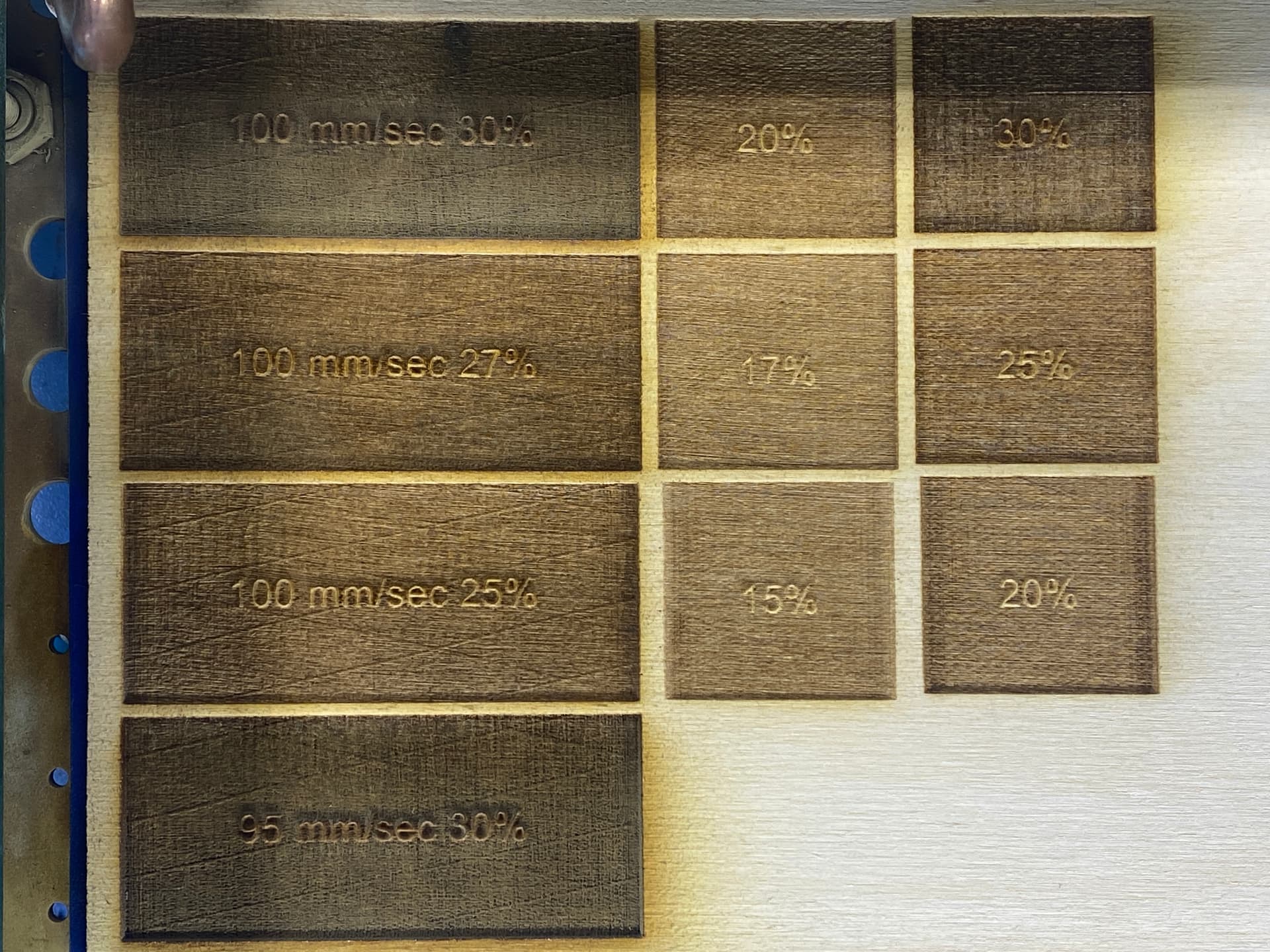
I like to tinker, and couldn’t wait a week to figure this one out. I have Pololu DRV8825 steppers on the Arduino CNC shield. I had set the steps to 1/32 when I originally setup the board. I just switched the X and Y axes to 1/16 and this is the end result:
The last column is with the new stepper settings, it appears as though this has solved my issue. I just hope the loss in stepper resolution doesn’t effect the visual output of the products I make.
Side note, I have no idea why the third rows boxes are skinnier, they are all the same dimensions in Lightburn. Probably has to do with the crappy K40 frame… (edit: overscanning wasn’t enabled on that layer)
Edit #2: jumped the gun on the fix. It still happens, just seemingly a lot less / irregularly