Under shape properties what is the power scale used for

Under shape properties what is the power scale used for
Thanks
Nicky Norton

1 Like

Thanks Jeff :ok_hand: :ok_hand: :ok_hand:

I would find this power scale to be more intuitive and less prone to human error if it were:

  1. Renamed to Power Override

  2. The value provided by the user was the actual value desired.

To make this happen (and having no idea what the underlying parameters are this is working with), I am thinking of this “current state” and my “desired state” represented by this equation:

Current state:
(Solving for shape power - where the user must take into consideration the layer power and calculate the correct Power Scale on their own in order to hit the desired shape power)

X = LayerMaxP x Power Scale

So at a 40% layer power, a person must think “I want this shape to be 20% so to get that I must figure that 50% of my current 40% layer will give me a shape power of 20%.

My suggestion (that may not be possible especially if the max power setting is a hard ceiling):
(Solving for Power Scale - Where the user simply specified the desired shape power and the computer calculates the parameter of “power scale”)

X = ShapePower / LayerPower

And with this, a person can just think “I want this shape on this layer to be lasered at 20% power. See, .2 / .4 = .5

This would be practical even more so if power scale can exceed the layer max. Such as

.6 / .4 = 150%

Power Scale is done using the commands that the DSP controllers use for ramp mode and grayscale output, so it’s explicitly limited to being a percentage of the value between min & max power.

I could, conceivably, have a power override, but there would be pretty rigid limits on the usage because of the way the DSP controllers work. I can change power for an entire set of cuts, for example, but not mid-way through a cut like I can with power scaling. With power scale, you can do this:
image

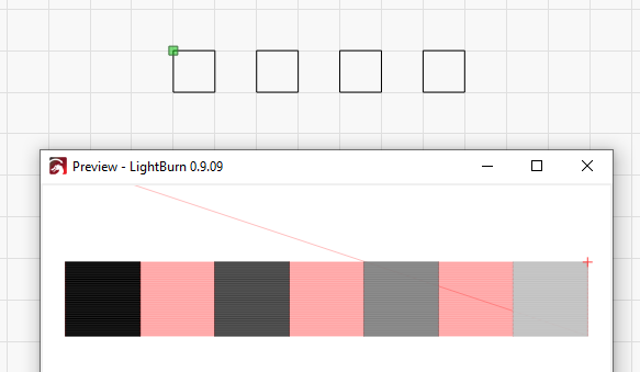
That’s four rectangles, scanned in one continuous sweep, with different power values. If I did that with a per-shape power override, I would have to scan each rectangle individually, and that adds all kinds of complexity to the code that validates settings, handles the fill options, etc.

Now that’s handy info, right there and explains why my test card didn’t do what I expected.

So if I had ten squares set to fill at ascending intervals of ten percent power, and my min/max was set to 10/85, what value are the first couple of engravings going to be at?

It could be 85-10 x .1 or 85-10 x .1 x .85, or something else entirely. Is there a way to find out the specific power setting for each power scale iteration?

In math, it’s this:
Min + (Max - Min) * PowerScale

And it’s also subject to the ‘Start Speed’ issue, so if you’re cutting at or below the start speed, it’s only using Min Power.

The simplest way to think of it is that Power Scale is a slider / knob that goes from Min Power to Max Power as the Power Scale moves from 0 to 100.

1 Like

With Min & Max set to 10 / 85, the delta between them is 75%, so that’s what you’re scaling. If you had 11 squares, with the scales of 0, 10, 20, 30, and up to 100, the equivalent Max Power values would be:

Scale Output Math
0% 10.0 10 + (0.0 * 75)
10% 17.5 10 + (0.1 * 75)
20% 25.0 10 + (0.2 * 75)
30% 32.5 10 + (0.3 * 75)
40% 40.0 10 + (0.4 * 75)
50% 47.5 10 + (0.5 * 75)
60% 55.0 10 + (0.6 * 75)
70% 62.5 10 + (0.7 * 75)
80% 70.0 10 + (0.8 * 75)
90% 77.5 10 + (0.9 * 75)
100% 85.0 10 + (1.0 * 75)
3 Likes

Cool. That tallies with what I was getting, but not understanding.

This topic was automatically closed 30 days after the last reply. New replies are no longer allowed.