@LightBurn can you say why LightBurn might be giving me the Cut is out of bounds warning and also possibly any insight into what may be causing these momentary motor pauses I am experiencing during the long side of my rectangles?
I checked that link and adjusted my current from 0.6 to the recommended 1.2 for the NEMA 17.
No change. Here is a video of the motor pauses I’m seeing.
Actually I am not sure how to tell if it does or not, I did some searching on the subject but did not find any definitive way to determine this. Here are the specs of my drive motor:
Yeah. I’m not getting much from that datasheet either. One thing I notice is that the voltage for this motor would be fairly low (1.7A*1.5ohms = ~2.6V).
You may want to compare this motor to the other ones on your machine and see how they compare.
Another thing I just noticed, When I run the test from the LightBurn rotary setup, I get smooth rotation without the momentary pauses, video here.
@LightBurn, I am also curious how LightBurn determines what would be out of bounds for my A axis, does it use the circumference set in the Rotary Setup window?
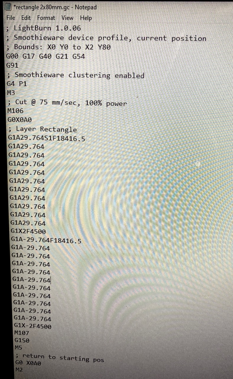
Not sure what it’s for but I see the one pause at the start of the job:
G4 P1
I don’t see any other explicit pauses.
If I’m doing my math correctly it would seem the circumference in the g-code is 327.404 mm (29.764mm * 11 iterations). I’m not familiar with A-axis operations or rotaries much in general though so not sure if there’s more nuance to this.
When you see the pauses does it correlate to the 11 relative move operations in one direction and then 11 again in the opposite direction? That could be the source of the pauses but unclear why that would cause a delay. So 22 total pauses in the whole job?
If you are using a chuck type rotary, the software needs the circumference to compute ‘surface’ speed. As it will change as the diameter changes.
Not so a roller/wheeled rotary, the drive wheel is what rotates the object and it’s surface speed is know by the step/rev, the gear ratio and the drive wheel size. There is no need for a diameter. No matter what the diameter, the drive wheel moves a known amount.
When I looked at your screen shot of the out of bounds…
If the position displayed at the top is the ‘current position’, 280x130, then trying to move it 135mm further would that put it ‘out of bounds’?
Just think of it as your Y axes, would that go out of bounds?
I don’t know what it takes to change from rotary to Y table. If you can generate the error then switch back to standard mode, I’d bet the error is still there…
@berainlb there are indeed 11 pauses in each direction! Just as there are 11 entries in the g-code in each direction… the question now is, why are there 11 entries for each direction instead of one?
I know zero about g-code and have not been looking at it up until now, so I don’t know if that is the way it’s supposed to be. It seems logical that those 11 entries up and down, are the reason for the pauses in my drive motor.
These are correlated then but not necessarily the cause per se. The commands should be fine but it’s odd that your laser is pausing due to them.
In reality, though, I assume you’d be running scanning operations, though, not operations that roll the object back and forth. So maybe this isn’t an issue in practice?
Hi jack, you are correct about current position’, 280x130 and what you say makes sense.
I think I may be confused about a few things here.
The first thing is, if I tell the LightBurn Rotary Setup I am using the A axis, shouldn’t LightBurn ignore the Y position?
The reason I wonder about this is that, to set my rotary, physically in a usable position in the bed of my K40 mini, it winds up being a bit above dead center in the Y’s usable area… if that makes sense.
So when I position my laser head over where it needs to be on the glass to start the engrave, Y winds up being about 130, when in reality that is my origin of my rectangle, where the glass will start spinning to execute my design which will most likely be larger than what LightBurn thinks I have left in my Y travel since it thinks I am starting at Y 130.
That is mostly the case, but what if I wanted a line or rectangle underneath a design or text on my glass, I am fairly certain that unwanted results would happen with the laser staying on at power while the motor is pausing at intervals during the engrave of that line or rectangle.
My assumption was that you’d burn an entire line at a time including line or rectangle underneath the design. Basically like a raster across the entire distance. This way you wouldn’t be dealing with any issue with rotational pauses.
I really depends on how your hardware is built. Can you leave the rotary plugged in and use the Y axes normally?
My setup, after the controller boots, I unplug the Y axis and plug the rotary in there. So the Ruida doesn’t know… As far as I know the only manipulation is computation of the motor steps to get the job done.
This is how I engrave a cup/mug…
The left side will be the ‘base/bottom’ of where I want the image. Center allows me to put the handle straight down for an image opposite the handle. Don’t let the photo fool you, it was taken before I fixed it and is ‘flipped’… need to get out and take another photo…
‘Start from’ set to User Origin
‘Origin’ set to center left.
A mug with a logo, the ‘origin’ is right above the center of the logo…
I rotate the Y axes (A axes, in your case) to the center of it’s range. Set the ‘Origin’, this is the ‘User Origin’ that the machine will use.
Now that the rotary is ‘centered’ I put the cup/mug in and orientate the cup/mug, not the rotary, it to where I want the center bottom.
My image can go +/- from that position.
Framing should work properly.
You will forget to set the Origin… we all do…
Does you controller allow you to use both the Y and A axes at the same time? Do you ‘hand’ set the Y axes or does you controller allow you to do it while the rotary is in the machine?
The way my machine works, I put it where ever it’s most convenient to use.
The only thing you need watch is that there is enough room for overscan in the X direction.
Vectors are tough with these and I have a configuration file that I load when I use the rotary, above that which Lightburn does. All of the ‘rotational’ speeds and accelerations are slowed, sometimes to single digits. Mine are in mm/s.
I generally just convert them to a bitmap and scan them for a quicker run. This really slows the problems axis, which is the rotational issue.
There are a lot of things I don’t know about your controller/hardware, so keep that in mind. I’m sure any blunders will be pounced on…
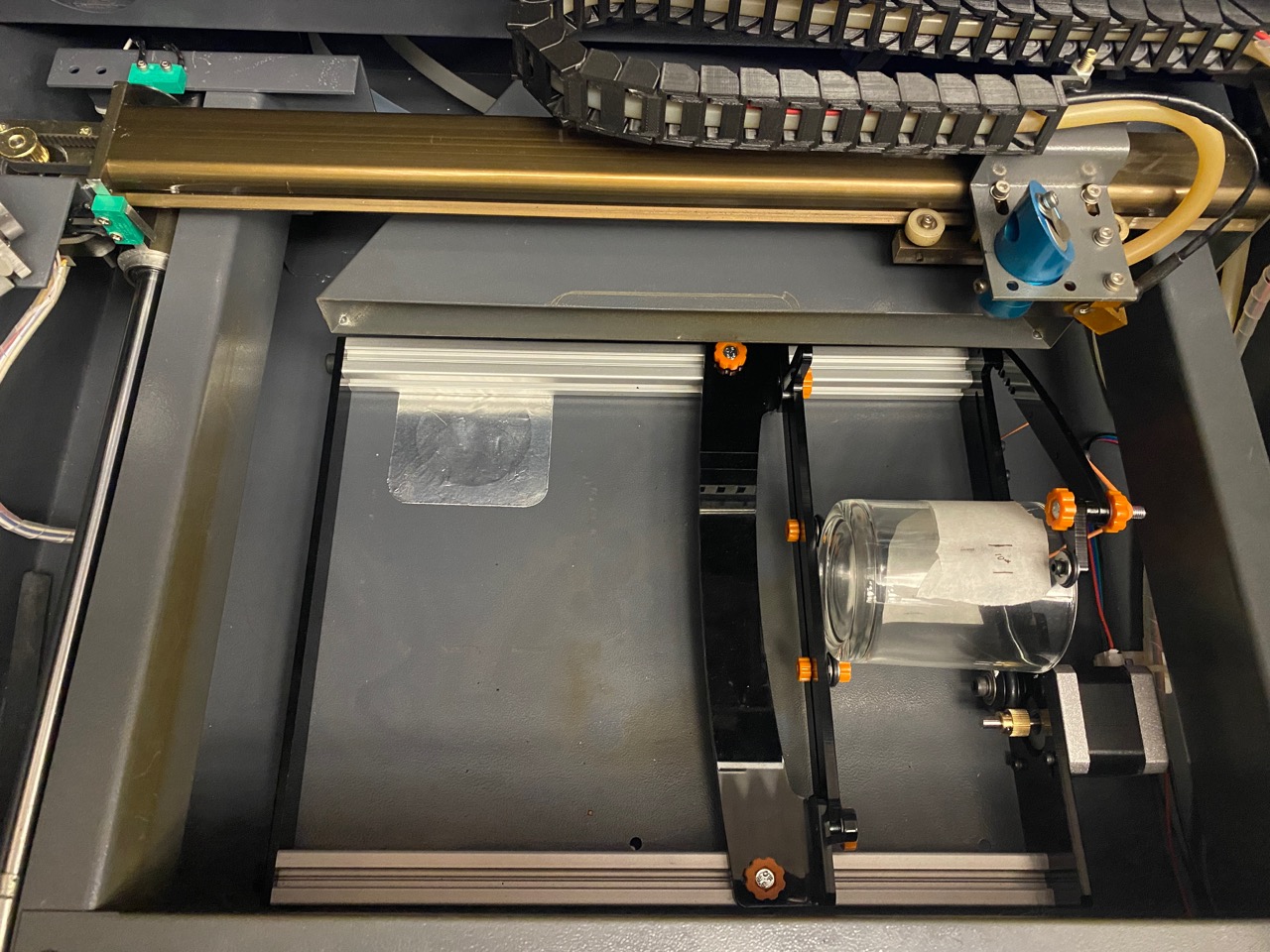
This is my PiBurn. It’s oriented backwards in the picture. I have since swapped the field windings and it sits with the motor on the right.
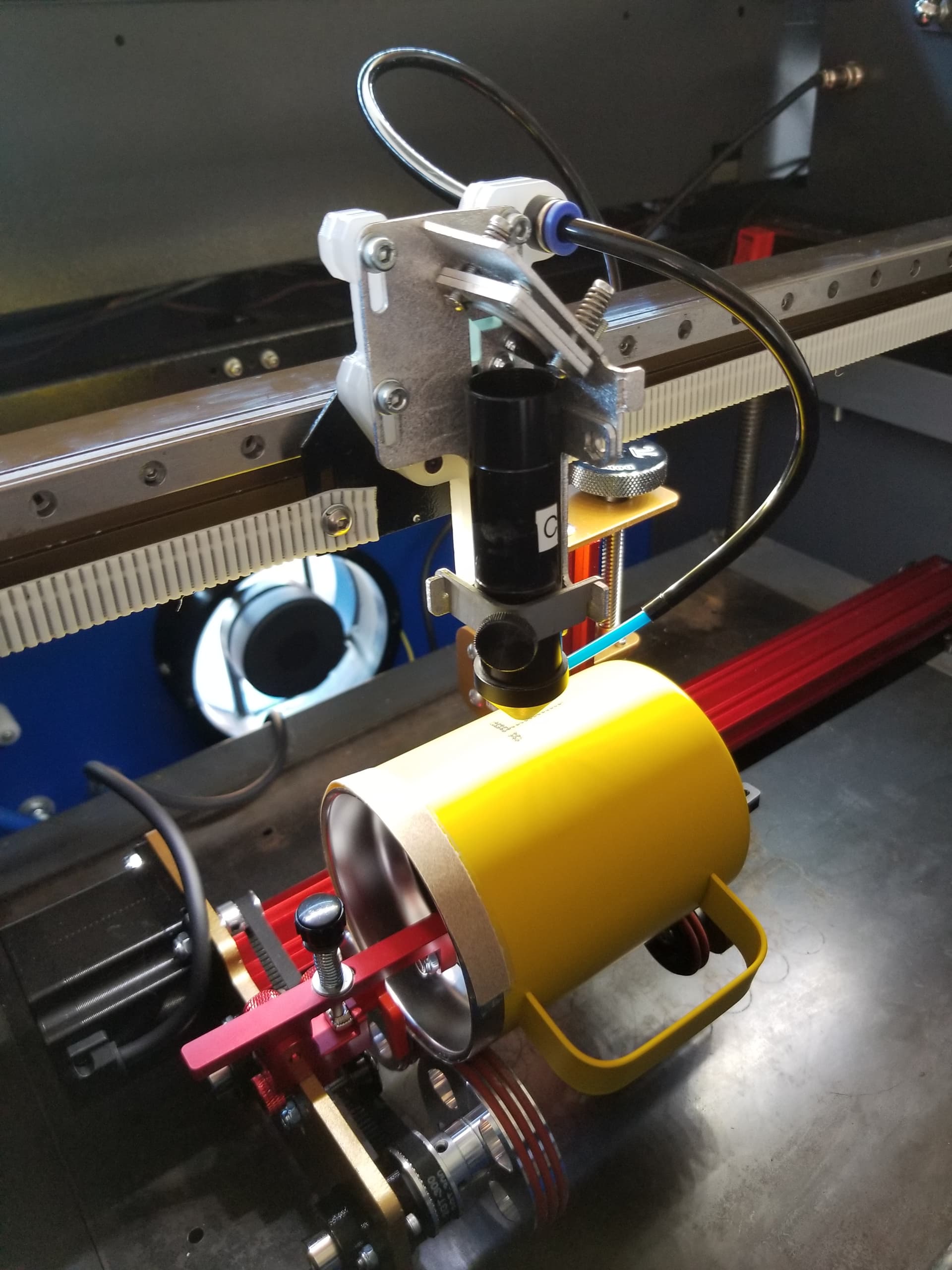
You are exactly right! I hadn’t thought about it like that… it’s great to have another set of eyes looking at the problem. Here is a picture of my first glass (line included) :
Although I am not quite happy with the results yet, I am sure this is just going to require a bit of fine tuning.
The bottom line is, it seems like the rotary is working!
Thank you so much for working through this puzzle with me @berainlb !!!