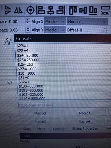
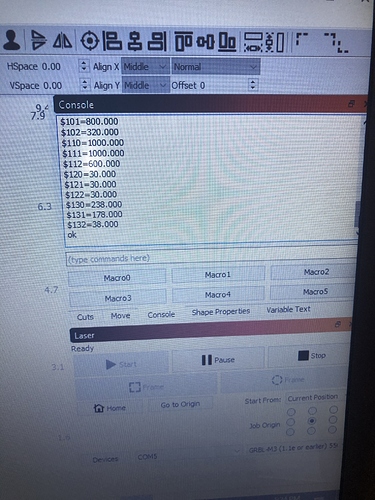
Yes i do have limit switch’s on the Z axis as I had mentioned, my question was do I need to turn another setting on to combine the Homing and hard limit? which if I’m understanding correct the hard limit is just a set of limit switch’s on all 3 axis, I’m completely new as I’ve said before and as a result lack the words and or knowledge to look up what I’m having trouble with. Which is why I’ve been bothering y’all, which I do apologize and thank y’all for your time and support  any help on my problem would be greatly appreciate
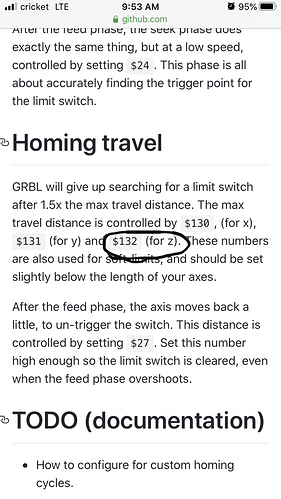
Homing uses the hard limit switches, so there shouldn’t be an issue there. I haven’t done the wiring for it, but you might need to adjust your configuration. The grbl docs have some specifics for setting up homing that might help: https://github.com/gnea/grbl/wiki/Set-up-the-Homing-Cycle
Okay thanks I was wondering if I needed further setting up, in that link it also gives the commands for setting the Z axis which I didn’t set up, because in the commands it shows the Z axis set to 200mm  when the Z axis travel is ONLY 40mm
 I’ll get that set as well. Thanks for your time and support
Okay thanks for the info I was able to get all the settings that Where pointed out on that link updated here’s a video of my problem https://youtu.be/uzN3Ts-BpgA
The only thing I can think of is maybe you don’t have the Z limit connected to the Z limit input? Z has to be pin 12.
You should be able to press and hold a switch and then type ? on the console and have GRBL report which limit is hit as part of the status message. That might help you sort out what’s going wrong.
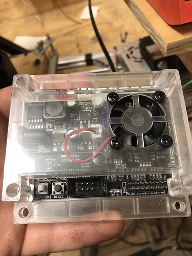
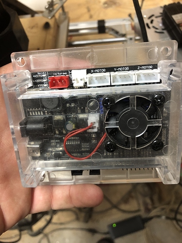
Well this isn’t a Arduino, it’s just a GRBL Board here’s the a picture of it, it’s a woodpecker CnC camxtool .
I’ll tryout what you’re saying. Get hub seams to mainly deal with Arduino and Arduino/GRBL combined at least as far as I see when I’m trying to look for a answer to my current problem. Thanks for your time and support
I tried pressing and holding a limit switch and typed ? And nothing happened besides it posting the alarm 1 and the ? Nothing else popped up hmm  weird. I tried both ways of putting the ? after pushing and holding the limit switch and then typed in the ? Then pushing the limit switch. I’ve been trying to do my own research but am having no luck
  thanks again.
Thanks for your time and support I just found out from gethub that this version of GRBL has the X and Z axis switch so once I change them my homing works, that might be something to save for future guys like me  now should I open another topic up because now I’m trying to figure out why my laser won’t burn it has a blue light when I turn on but it doesn’t burn, is that normal? Thanks again
Check to make sure it’s in laser mode ($32=1) and the other stuff listed here in the first paragraph: Documentation/CommonGrblSetups.md at master · LightBurnSoftware/Documentation · GitHub
Okay I entered that command in and still nothing happens hmm  here’s a video of the a program running and the laser not working after I put the $32=1 to enable it. https://youtu.be/FoVyeFqINwQ
Right click on those macro buttons to change them. You can add arbitrary gcode to be executed to automate whatever you want.
I’d say you have your laser wired incorrectly.
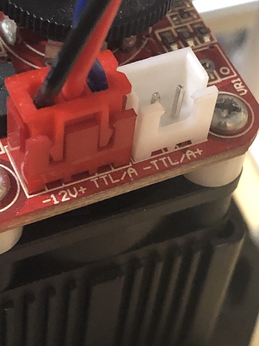
The white connector can be ignored, that’s for direct TTL control but you want PWM which is what the red connector is for. But it seems to be on all the time. On the red connector it should be labeled 12V- (or gnd), 12V+, and TTL or PWM. My guess is that you have the 12V power connected directly to the PWM line or something. Also, that wheel on top controls the max power. If connected correctly, turning that wheel a bit past the initial click should not turn the laser on at all. Then firing the laser should actually turn it on.
It appears you have the “Fire Laser” button enabled. Use the wheel on the laser to turn it on a little ways, and then set “Fire Laser” to ~5% and click the button. Assuming everything is wired right after you recheck it the laser should remain off until you have clicked that button. Click it again to turn off.
Once that works, then you can just turn the wheel all the way up and leave it there.
Okay I’ll try that, though you got me a little confused check wiring lol  it’s only one set of wires that goes to a red laser input on the GRBL Board. Thanks for explaining macro.
Well that stinks, I just blew my GRBL Board, I tried flipping the ends of the 3 wire connector because I noticed the wire color would be in a different order on the inputs, DONT DO THAT  it caused a electric fire
  the blue wire stran needs to be on the left side not the right side, I guess I’m back to the drawing board
  got to set up another board lucky I have a second one, just need to get its settings set up now.
 My point was to check the labels on the controller and the labels on the laser and make sure that everything matches correctly.
Not sure what you mean by the wire color being in a different order… as long as the 12V wire goes to 12V and the PWM wire goes to PWM, etc you should have been fine.
Can you take pics of the laser output on the controller and the laser input on the laser?
Yes I can, I’ll do that once I get out of work, I just left the house for work. lol ya  I’m really glad I’m messing with a $200 CnC rather any real cnc machine, a mistake like this one I did is only $35 instead of $3,500+
  . Thanks again for your time and support
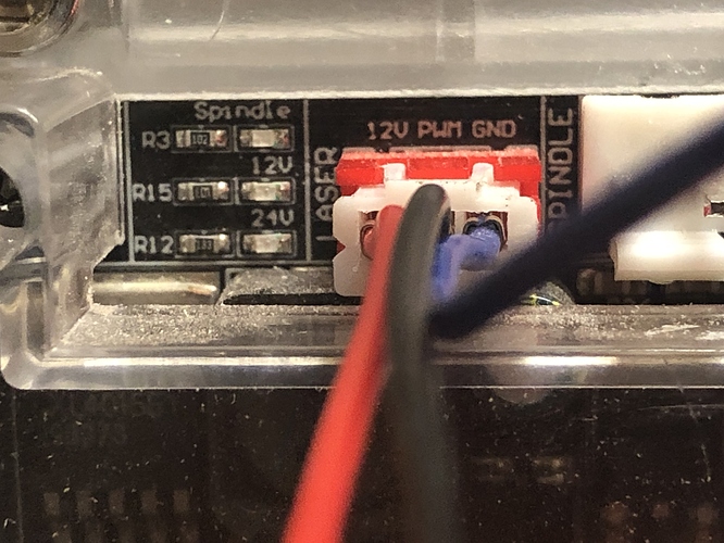
Here’s the pics
now I’m re-configuring my new GRBL Board so we will see how that goes lol see how much I remember
Oh yeah… those are wired wrong! you can’t really trust the cables that come with those lasers!
Note that your laser module is:
Ground | 12V | PWM
But your controller is:
12V | PWM | GND
Also, no idea why the wire colors are in a different order on each end.
You’ll need to rewire one of the ends. If you don’t touch the red (laser) end, then you need to rewire the controller side to be Red, Blue, Black. Just switch the blue and black wires on the controller side, leaving the red where it is.
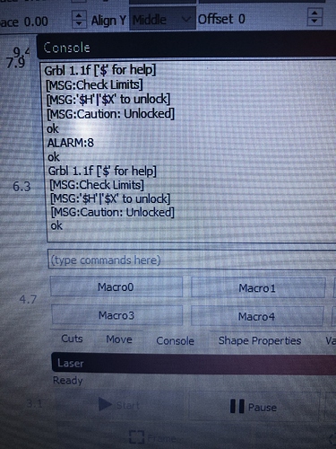
Okay so now my laser will actually burn something now that I have the wires soldered on right, though I still can’t control the power from the LightBurn software, as I did what you said turning it barely on and test fire at 5%. I’m setting up the new board and it won’t home, it keeps throwing this alarm
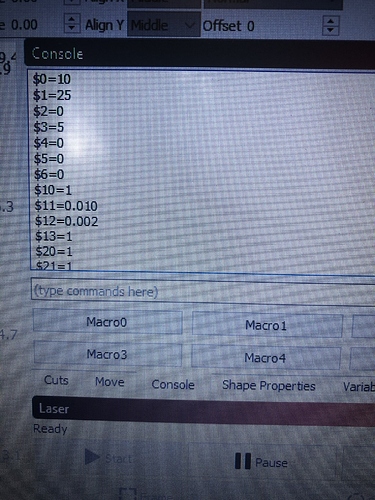
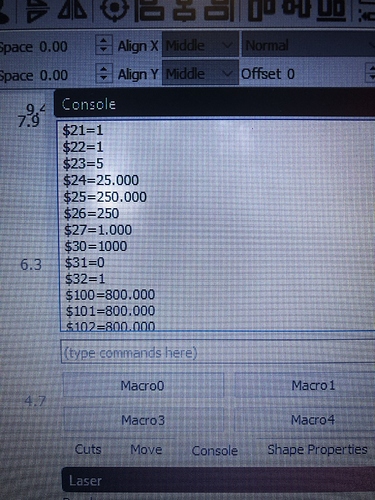
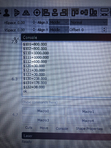
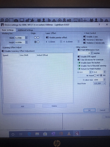
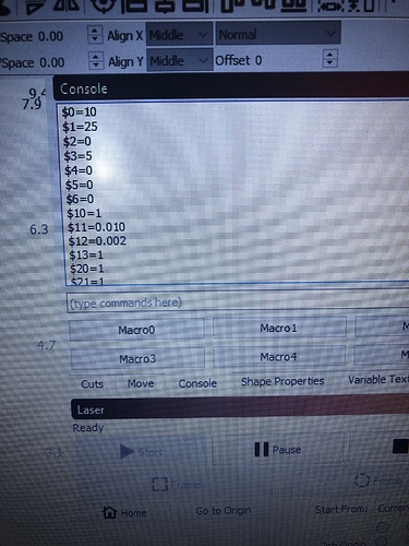
here’s my firmware settings, I believe i have everything set right.well, now you need to turn the dial all the way up and then control it with PWM from LightBurn. Can you at least make it turn on and off with the fire button in LB?
Also, highly recommend bookmarking this: https://github.com/gnea/grbl/wiki/Grbl-v1.1-Interface#alarm-message
You’ve got a homing error. Double check that you have all the same settings as before.
