Hi
I just want to say I am pretty new to the whole laser cutting experience however lightburn has made things a bit more easy to understand. Not like the other softwares…
That being said I am currently facing a few problems.
I have a 100/100 cm laser engraving but as of now I just can’t seem to get the workarea to match with the workspace of lightburn even though I did the set up at the beginning. Anything I load up work in lightburn to be framed or engraved in some cases, it causes the motor drivers to skews off to the left or top or bottom corner of the engraver thus in turn grinding my belts.( I hate that sound ) please help!!
I have a 15 watt laser diode I got of ebay with ttl module, I first powered it with its own power source and it burnt through 5mm thick cardboard at a distance of 7cm ( it was out of focus but still powerful), then later hooked it up to the engraver board but I can’t even get it to cut it through, only kiss cut it even that I’d need two passes, full power and at a speed of 2(in/m).
The current firmware to my knowledge is
Grbl_v1.1h.201908.hex
Previously I was using these
Grbl_v1.1f.20170801.hex
Grbl_v0_9g_atmega328p_16mhz_115200.hex
however it started acting up not sure which one but whichever, it caused the laser to fire when it was uploaded.
Im currently running windows 10 Pro
Im running lightburn 0.9.11 version.
This is the controller board of the engraver.
2 Axis Stepper Motor Control Board Driver For DIY Laser Engraver Benbox
Check Edit > Device Settings and make sure the ‘S-Value Max’ parameter matches the 1000 you have here. That would give you lower power if they weren’t matched.
For the framing issue, does the machine have homing switches? Does it home when you connect? If not, you’ll need to manually set the origin, or use ‘Current Position’ only when running jobs, because the machine won’t know where it is in relation to its maximum travel limits.
The s-value max had been already set to 1000.
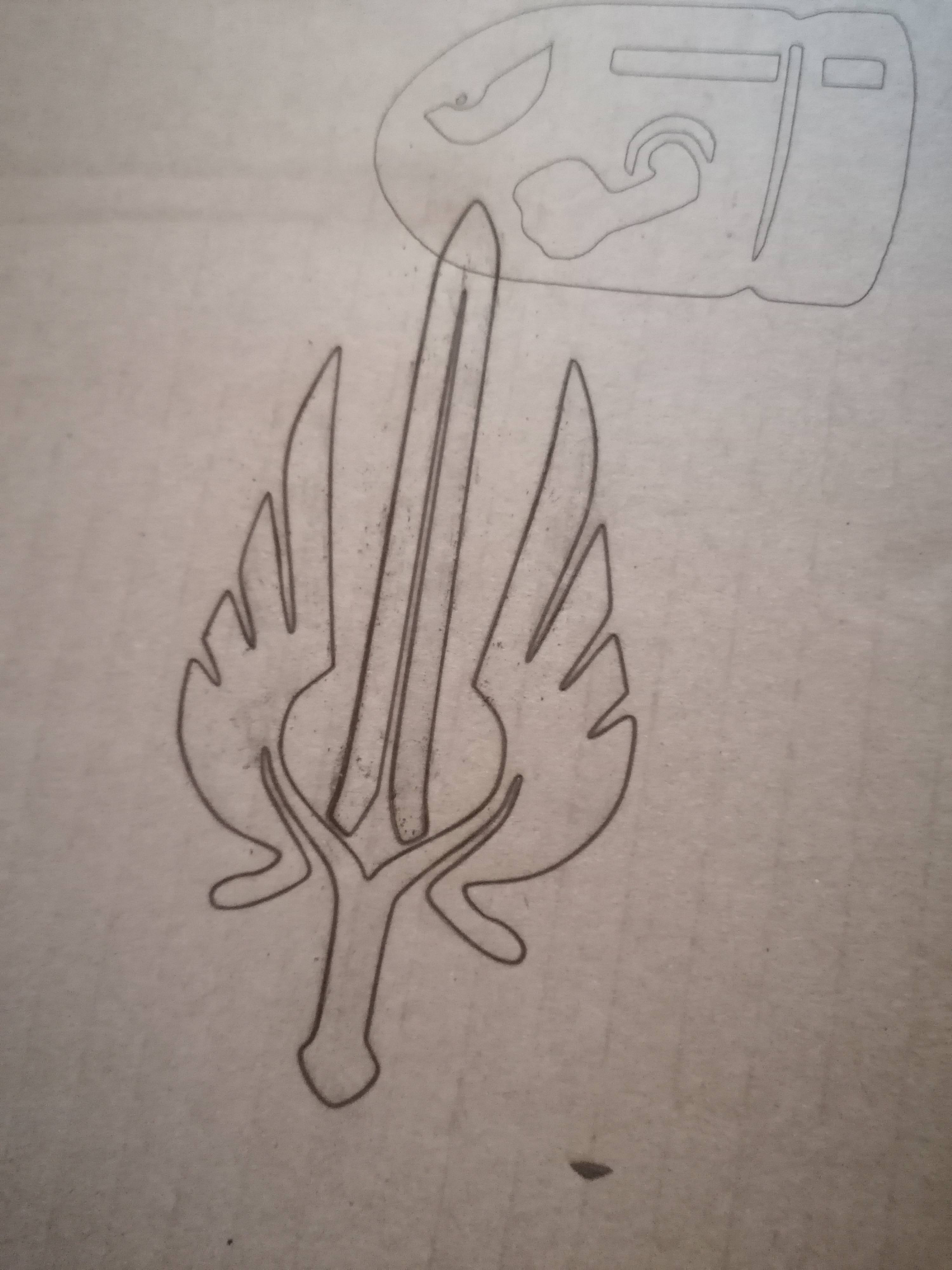
I just recently tried to cut this out of cardboard but it didn’t work. At speed of 1(in/m) with two passes.
But how do I get the job on the screen to reflect on the workarea because if I increase the scale by just a bit on the pc and frame it, it tends to come out over sized on the workarea. Hence the motors at times trying to over step workarea.
Can you please guide me on how to match the grid area in lightburn to my machine workarea.
I may have missed something prior to my initial setup. Since my machine working area is 100/100cm and lightburn is in inches I converted 100cm to inches for the grid size.
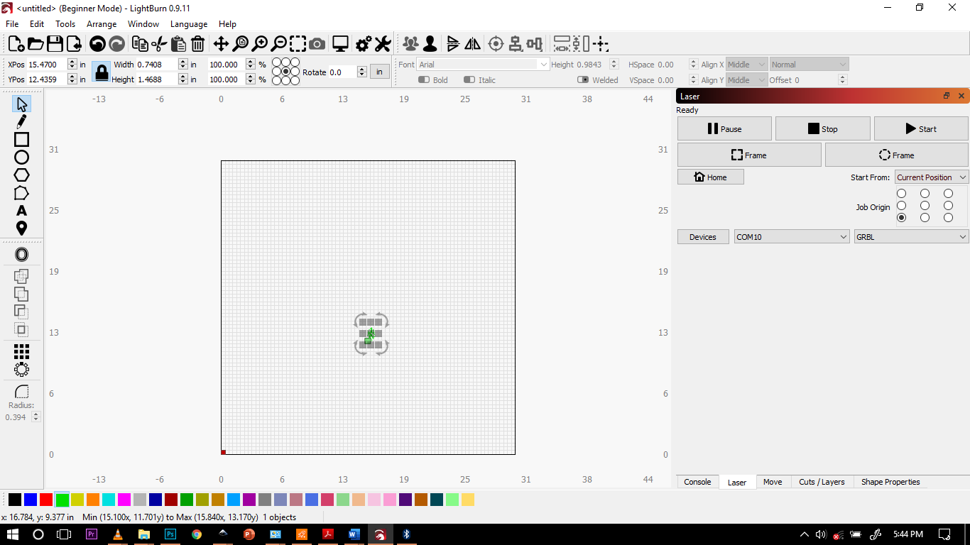
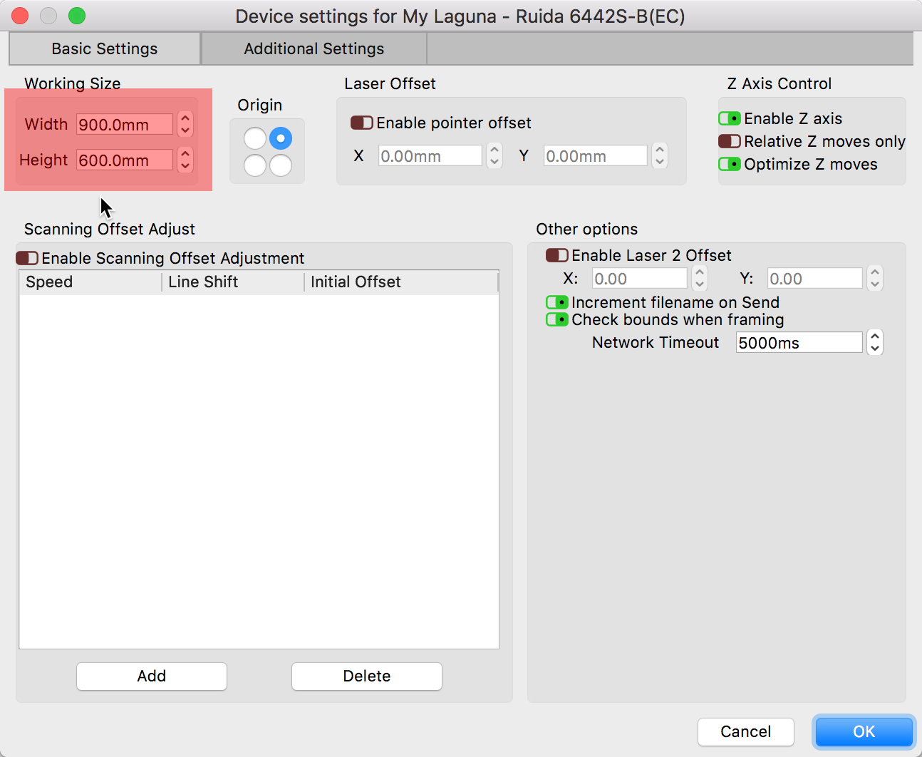
To ensure your LightBurn workspace matches the physical size of your laser, click the ‘Spanner/Screwdriver’ icon top-center of the main screen to reveal the ‘Device Settings’ window where you can enter the size values. (Screenshot is an example only, enter your correct data)
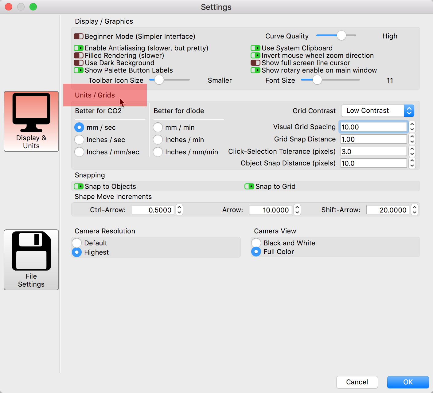
You can control the ‘Units’ of measure used in LightBurn to help with this. Click the ‘Gears’ icon top-center of the main screen to reveal the LightBurn ‘Settings’ window.
But I Still can’t match the actual size of the grid in lightburn to my workarea even if input the right work area size, and I increase my job size it doesn’t correlate to the actual size of my laser cutter…its almost as if things are shifted
As long as you don’t home the laser, this will happen because it has no idea where it is.
If you don’t have homing switches, it means that the zero point of the machine is random, in fact, wherever you have the head when you power the machine will be zero. To set the zero point properly, either power up the machine with the head at the front-left, or jog there and enter this command:
G92 X0 Y0
The above tells the controller “where you are right now is X0 Y0”.
If you use this command, you’ll also need to set $10=0 in your console, as this tells the laser to report its position relative to that new origin, instead of relative to where it was powered up. That value is ‘sticky’ and will persist after you shut it off, so you only need to set it once, unless something else changes it.
Tried what, exactly? This will go smoother if you tell us exactly what you did and what the result was in as much detail as possible. Saying, " I did that…" allows for a lot of potential misinterpretation.
You changed things, right? So I asked for the most recent view into your firmware settings. Example, your old $10=1, now after your change, $10=0. We can go back and forth as to why I am asking for the information so you will understand, but that will not change what I need to confirm as I try to help you.
Is it safe to assume you entered that into the LightBurn console? Where did you have the laser when you enter this? Did you do this before or after changing the $10 setting in your firmware?
Yes I keyed in the G92 X0 Y0 in the lightburn console. I had the laser at the bottom right corner then I have to jog it to the bottom left hand corner of my machine.
I did it after changing keying in G92 X0 Y0 and $10. Then I tried to frame a job which made to the motor drivers overstepping again.
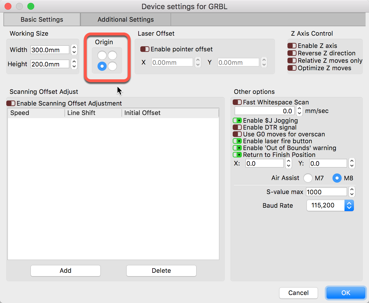
Set ‘Origin’ in the ‘Devices Setting’ found by selecting the ‘Spanner/Screwdriver’ icon near the top-center of the main LightBurn screen. This is the machine origin, not the origin of a job which can also be controlled.
So I switched off the board connected to the ttl laser. But the USB was still plugged in.
the origin was already set to bottom left corner.
But I noticed the my x n y above the air assist in the device setting were set to x=48 y=48 so I changed them to zero.
Powered laser system on.
Nothing happened at first but when I tried to frame again it went overstepping. However later…I tried jogging it back to the bottom left corner it stopped half way and wouldn’t respond…
Sorry, but I have no idea what you are saying here. Can you reword this, please?
I feel the need to identify that I am not trying to make this harder than it need be. I am trying to figure out what your system is doing and help explain what you need to change to get it to work. You took additional steps and made changes while I was trying to walk through a process to determine what is happening as I am not there to observe with my own eyes. Not sure where we are at this point.
Do you have any other software that came with this system? Have you tried to get things working correctly with that software?
I am going to offer this post as a suggested approach to help you get your system set properly. It is for a different system but these differences should not cause concern.
Read this, follow these steps and we can go from there.
 ) please help!!