Back on subject, What you thought you knew about laser diode control.
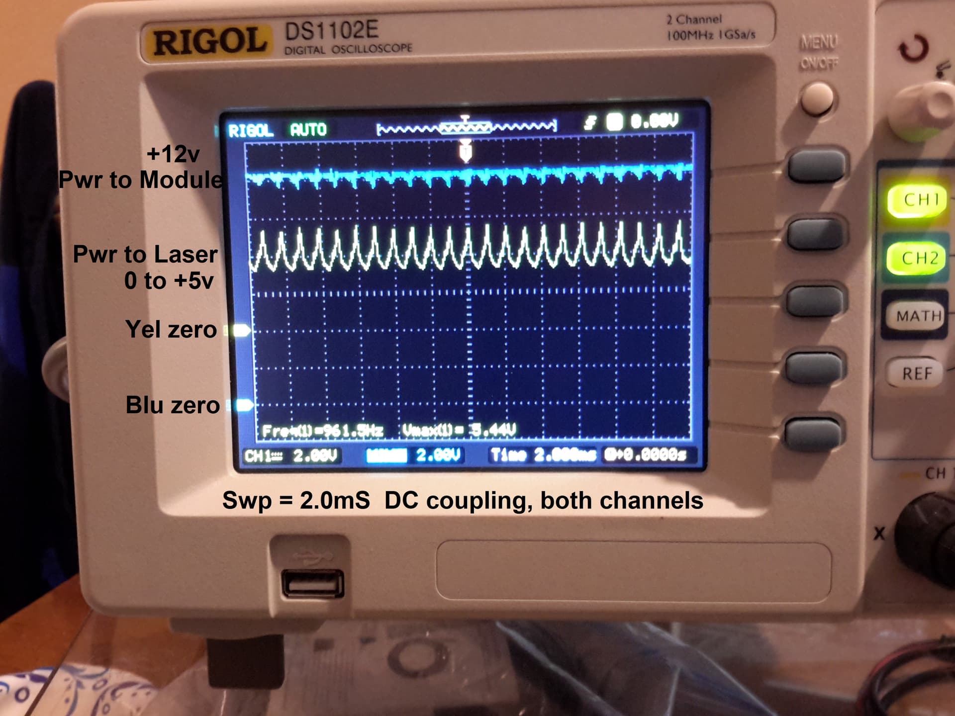
I ran some detailed tests on my machine and recorded the results. Rather than fill up this space with a lot of text, I reduced it to a text file and 2 images. The marker on the scope image left-center is the zero volts marker.
If I’m reading the timebase correctly (*), the horizontal scale is 1 µs/div, which is much too fast. Arduino-class microcontrollers typically run the PWM at around 1 kHz, so you may be seeing the noise between the pulses.
You can trigger the scope on the falling edge of the STEP pulse for a repeatable starting point based on the G-Code command or on the leading edge of the PWM signal for a starting point based on the laser control.
The waveforms may become more readable at 2 ms/div (-ish) with a solid trigger. Some samples of stepper motor drive signals to show what’s possible with neurotic attention to detail:
The usual CNC spindle control signal is 1 kHz (-ish) TTL-level PWM that the spindle drive demodulates to an analog voltage used for closed-loop spindle speed control. Some spindle drives will (also) accept a 10 V (-ish) analog input signal.Unlike laser power supplies, these are generally not on the same input pin.
Low-end GRBL boards (generally?) skip all that and have a MOSFET intended for direct open-loop PWM drive of a DC spindle motor. They route the motor current directly through the PCB, right next to the microcontroller. Hilarity ensues.
(*) C’mon, blow a couple of days for us discovering how to yoink digital screenshots outta that bad boy.
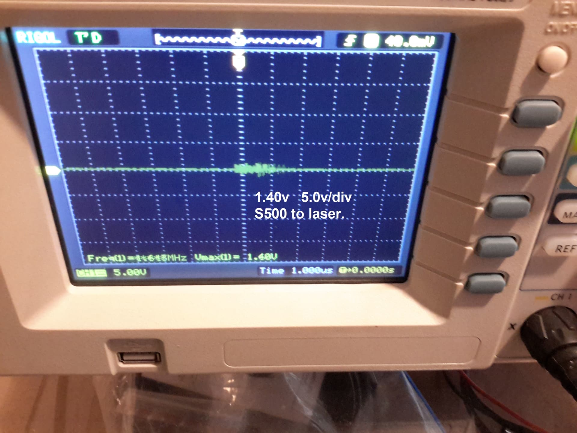
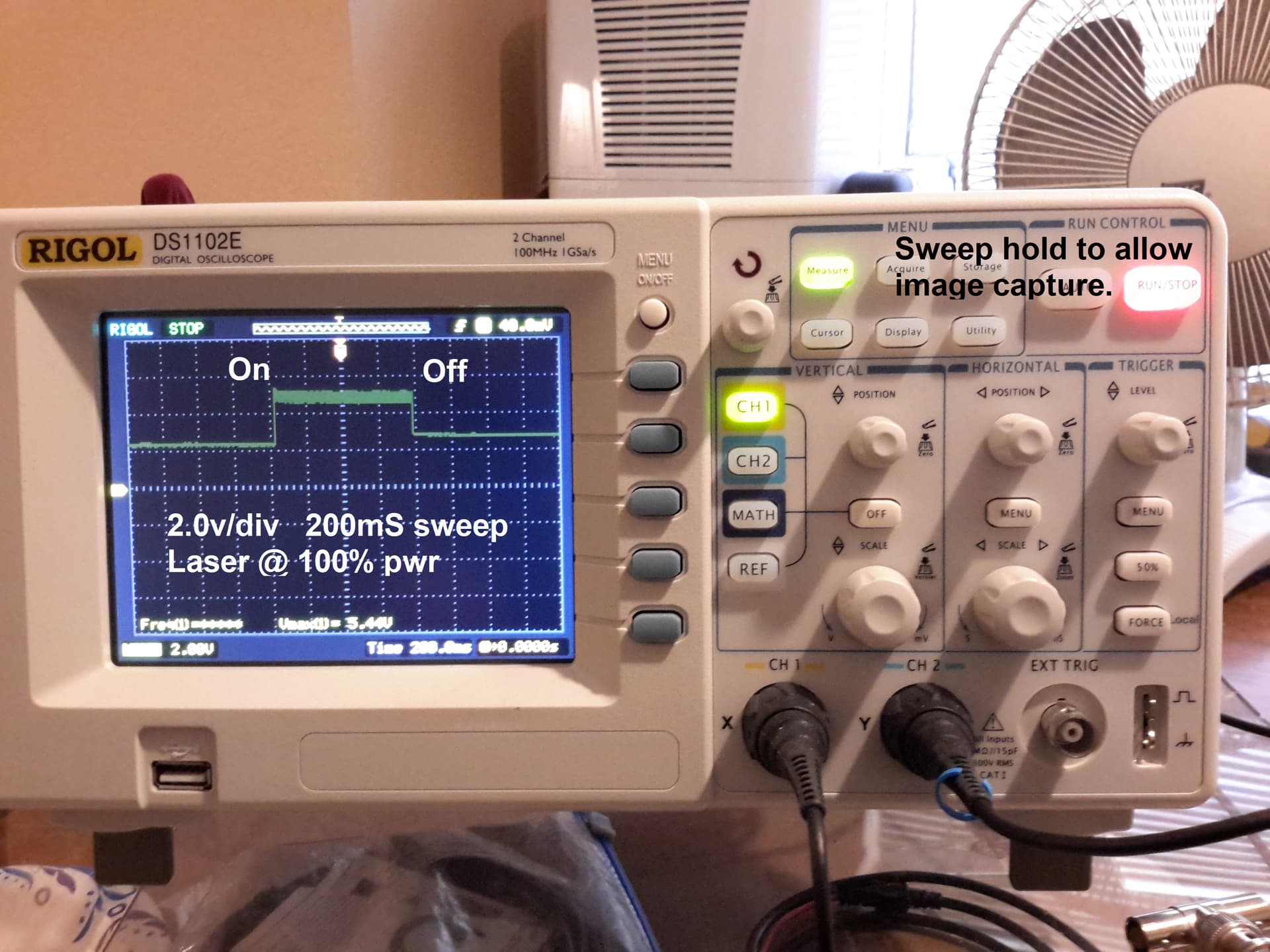
I slowed down the sweep on the presumption I might be viewing the top of a single PWM pulse. The image #-1 definitely shows there is no pulse activity during the On time. Voltage transitions would appear as a whitening under the raised waveform.
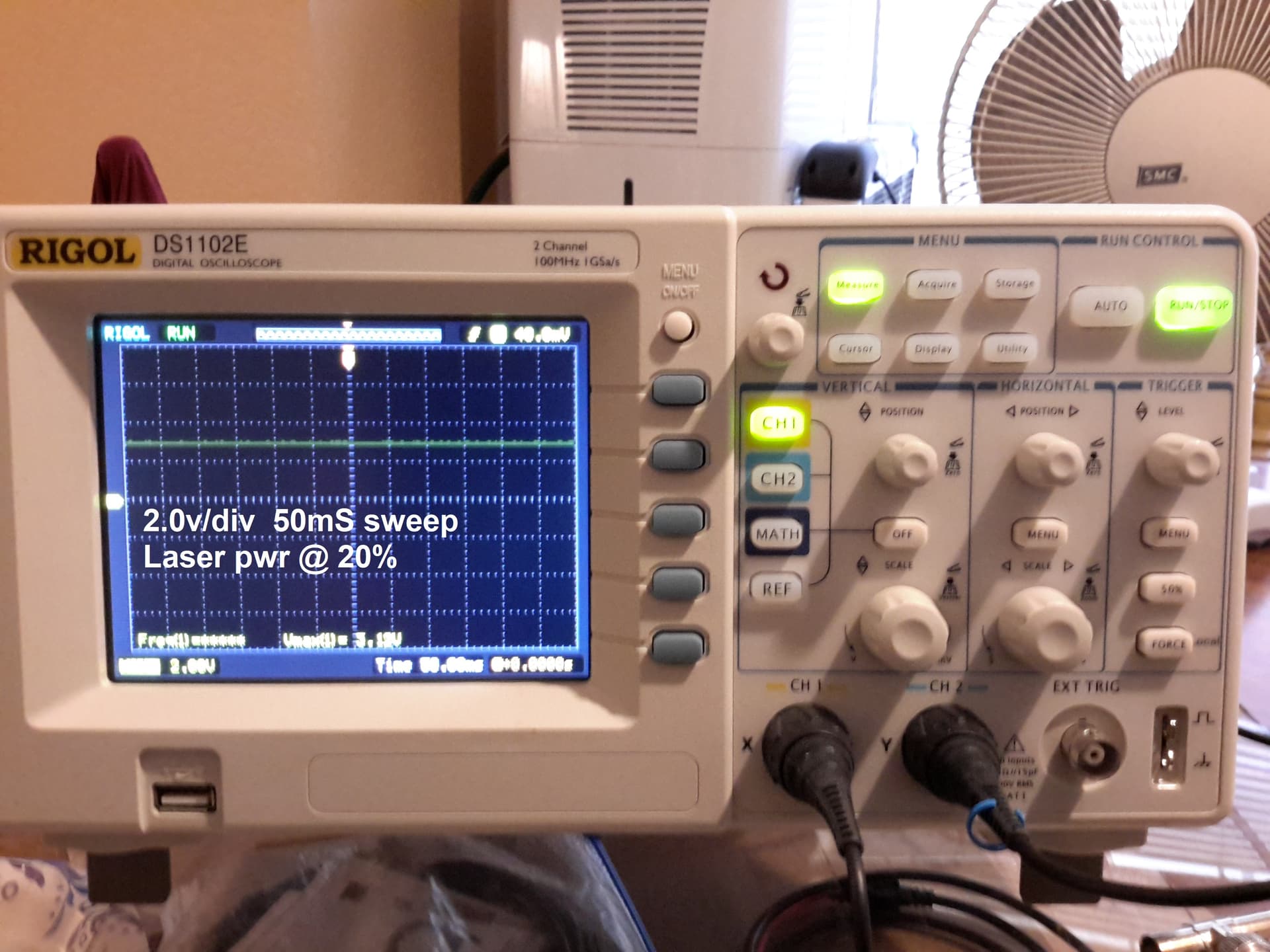
To ensure there was really nothing there, I raised the sweep speed, in image #-2, to spread out any possible pulse activity. Unfortunately, the sweep was too fast for me to push all the buttons fast enuff. Again, no waveform is seen below the voltage line.
I am just as disappointed an anyone else to learn this. Everything I thought I knew about Laser PWM Control went out the window. This is sad because I know a laser diode is capable of easily being pulsed at a 1KHz rate. PWM would be much more accurate for controlling laser power than a wandering DC voltage.
I am going to get out my ELEGOO Super Starter UNO R3 Project kit and find out if that dimmable LED was fed pulses or DC. And Raspberry Pi, you are next!
Assuming the schematic matches the actual circuitry (*), that explains much of what the scope shows.
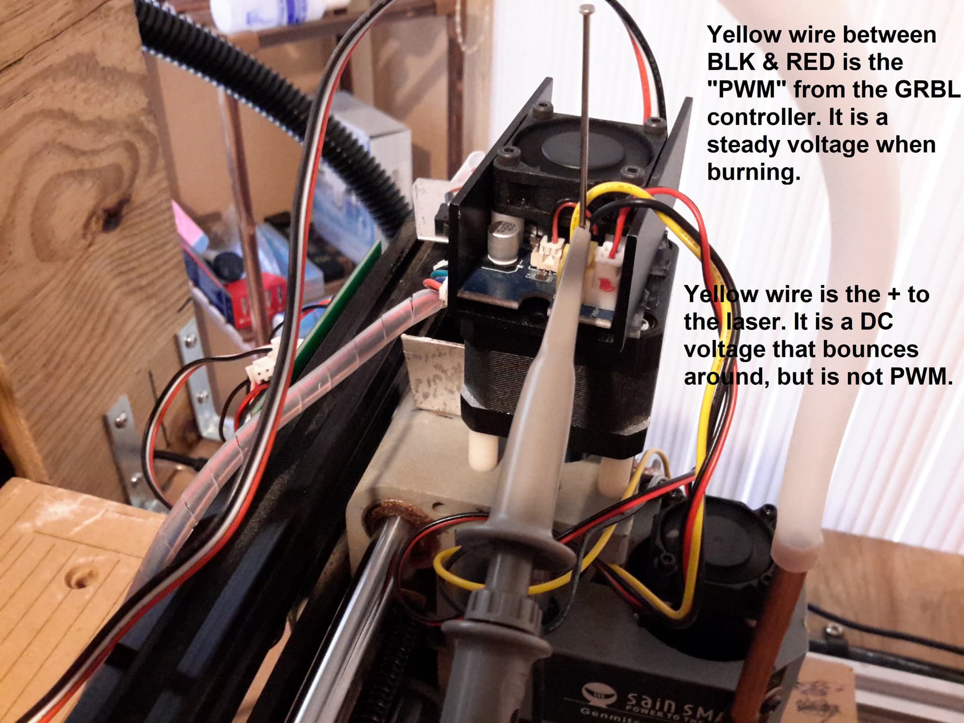
measured 8.65 volts to the yellow control “PWM” wire of the LCM. This was with no output of the laser beam commanded.
With the laser output inactive (and no 24 V spindle supply and no spindle motor), the MOSFET drain will float at some random voltage under 12 V (-ish) determined by the transistor IDSS leakage through the pullup inside the “laser”.
The assortment of stacked caps intended for the spindle will somewhat stabilize that voltage, but the signal isn’t actually doing anything. The scope’s AUTO function then desperately attempts to find something anything interesting to trigger on, so it proudly shows off those little glitches with a blistering timebase.
The scope did not show a PWM signal, but a DC voltage that varied a lot.
Dial the timebase back to 2 m/div, set the scope trigger to SINGLE with a falling edge at about 2 V, run the G01S500F50X40, and you should see a nice PWM signal. Might take some fiddling to get a meaningful trigger and maybe some zooming to see the details, but it’ll be there.
The 1.4 V DC-ish signal you’re seeing comes from the same pullup as above, but now the active PWM signal pulls it to 0 V half the time and lets it rise during the inactive half. Watching the voltage immediately after the MOSFET switches off will show the usual RC waveform with the 100 nF cap filtering whatever the pullup resistor might be.
Good clean fun in the shop and solving puzzles gotta count for something!
(*) It’s similar to what came with my 3018 board, plus the handful of suppression parts around the spindle output and minus the optioisolator (!) driving the MOSFET.
It would be helpful to know what the drive circuitry is doing in there, because it certainly doesn’t match any of my assumptions for a cheap CNC-oid GRBL laser machine.
It may be a knockoff Neopixel, in which case the control signal executes a peculiar self-timed shift-register dance:
If the LED has RGB colors and only three leads, that’s a clue!
On mine, the dpssl that came with it, was just that… no electronics, just a cheap dpssl that the mosfet completed the ground during the on cycle of pwm …
Mine is also Woodpecker 3.2, Sainsmart 3018 Pro with 5.5w laser accessory.
Because I can. It is a dual trace scope and that is Ch1 normally sits. Gain is adequate for the display.
No argument here!
Not at all, easy peasy.
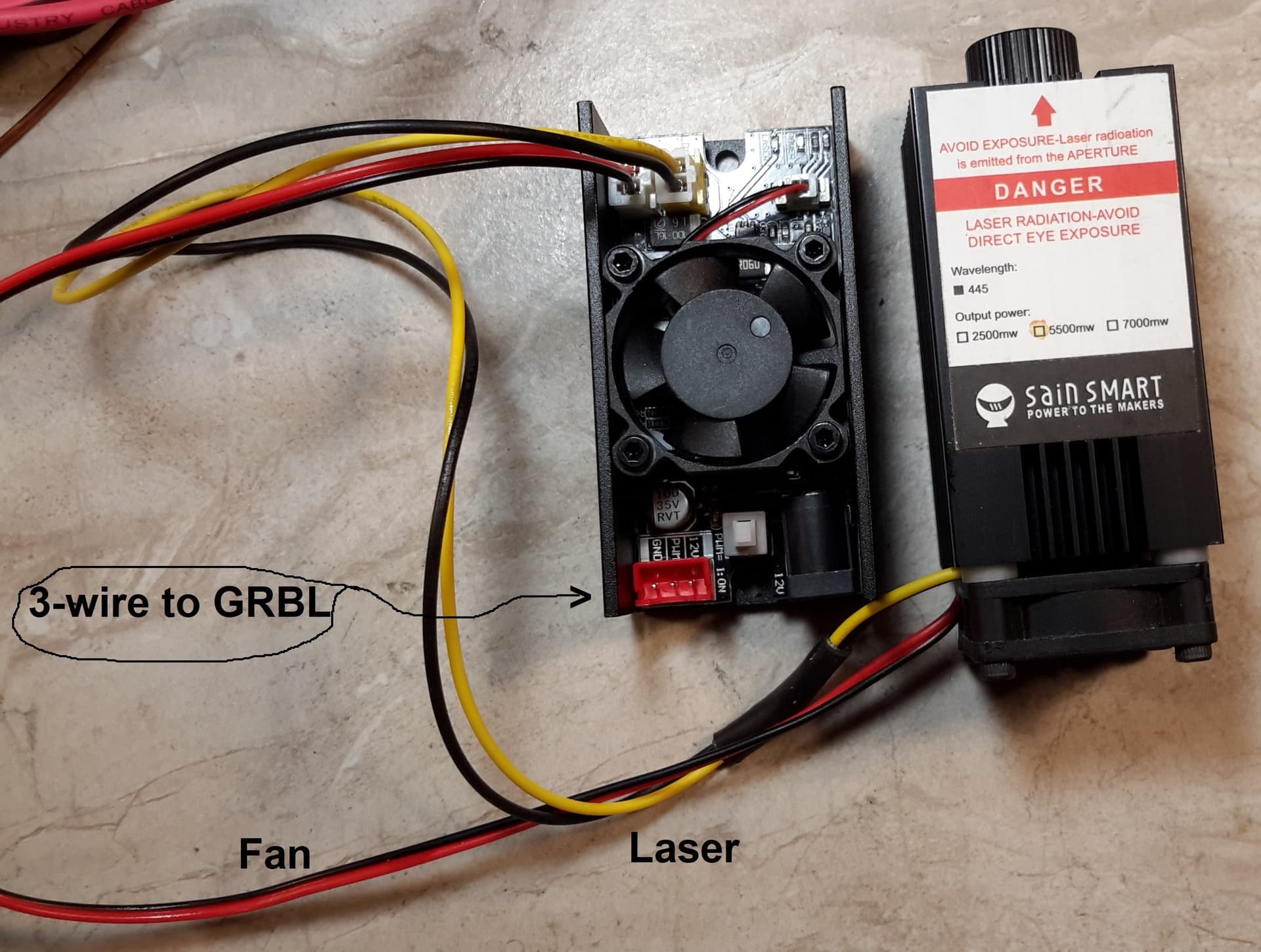
PWR to Laser image confirms this statement.
Enuff of the Q&A. Now for the latest results…
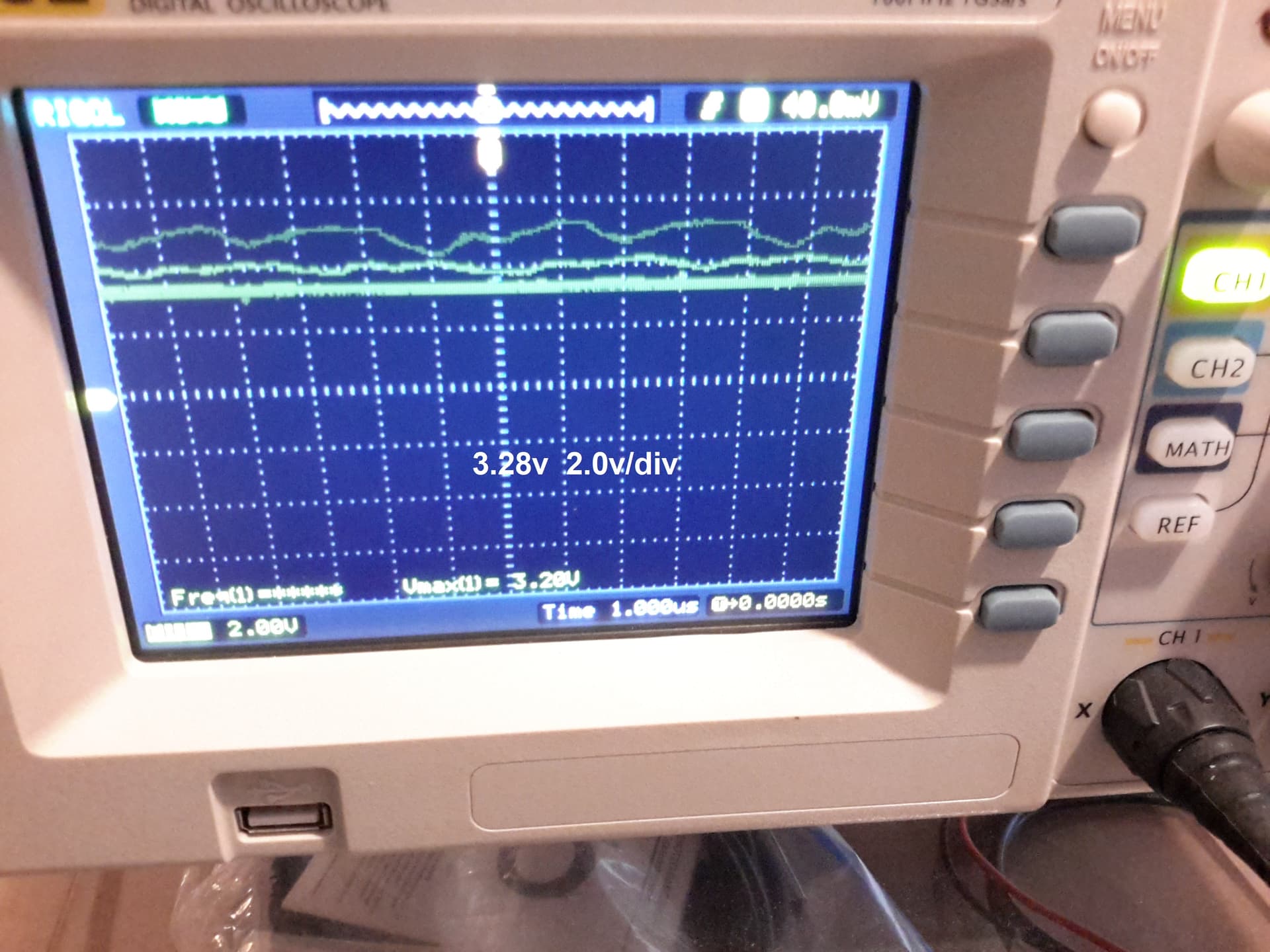
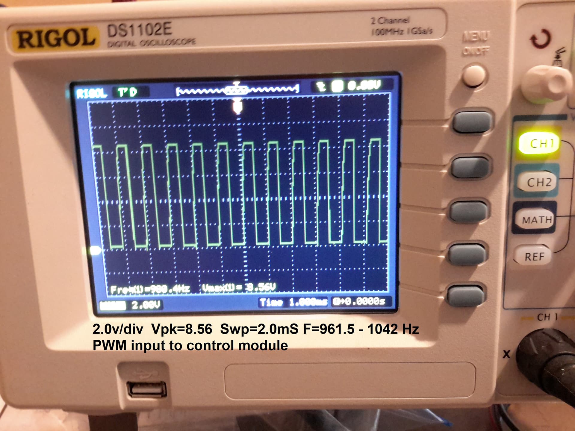
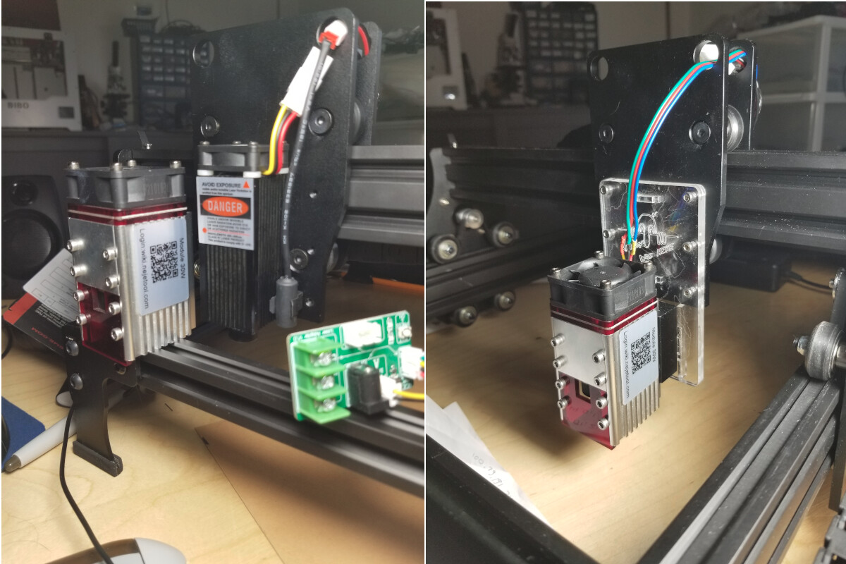
PWM to Cntrlr shows there is a PWM signal applied to the laser controller module. See image PWM to Cntrlr for parameters. The LCM is between the Woodpecker board and the Laser Module. See image Test Points.
In closing, I want to say it has been really fun trading notes with people having electronics experience. You guys kept pushing for accuracy, and I like that. If you have more ideas for me to try, bring it on!
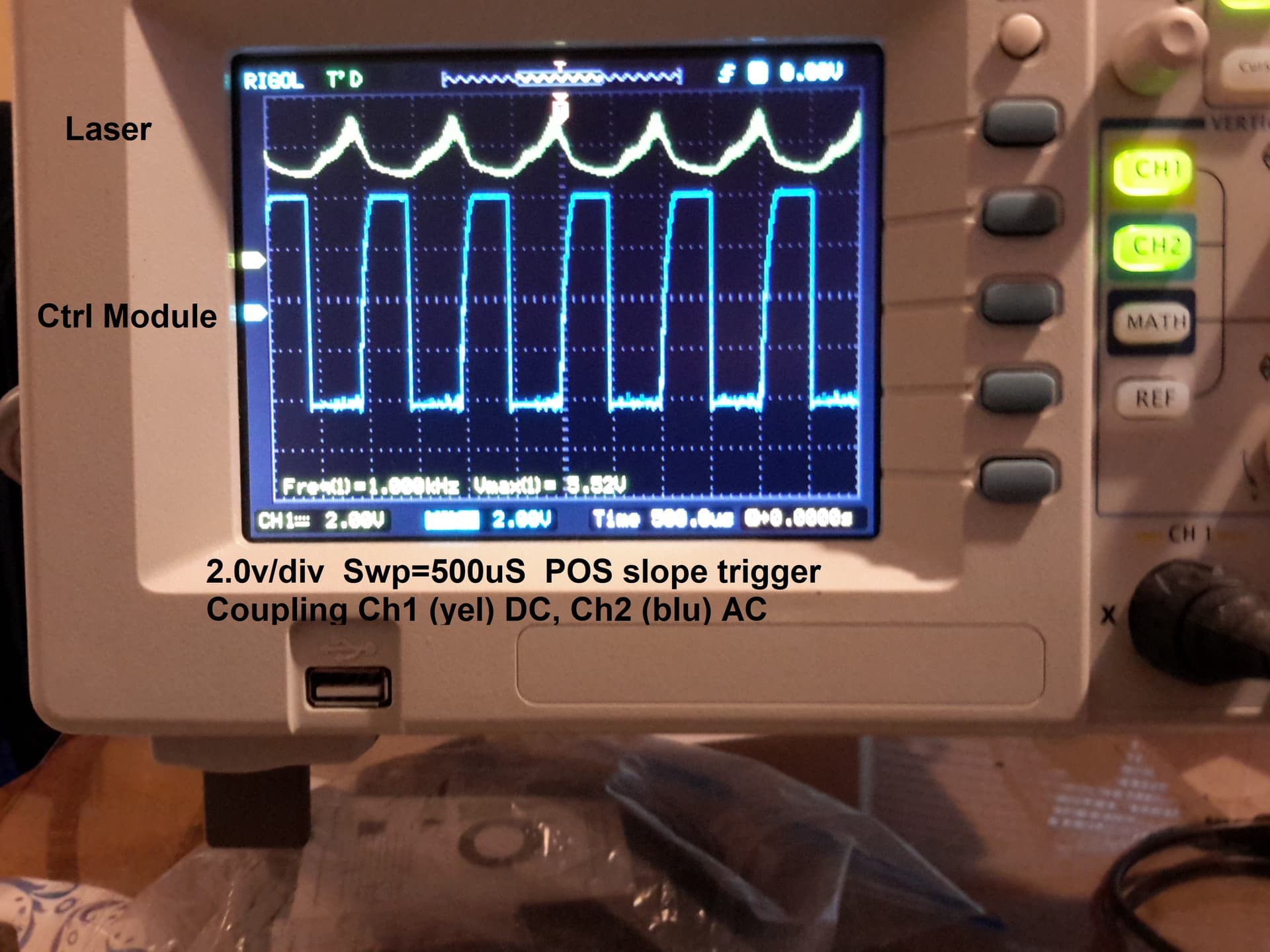
Put both 12V and PWM signals on your scope so we can see the relationship… if the 12V is dropping when the laser is supposed to fire, it might not have enough current available…
Where did you get this module and how are you supplying the 12V to it… it’s not a stock module?
I don’t know what the EMF referred … You’ve mentioned it and PWM to Cntrlr can you clarify what you mean… Cntrlr… figured this out… I think what threw me with cntrlr, was that the controller generates the pwm, not the controller…
Is there an interface board between the controller and the laser?
This next image is the input 12v to the laser control module. The 12v has some ripple, but nothing drastic although it may be amplified in the output. Should have bought the 4-channel scope?
Curious, @jkwilborn , does the 32-bit GRBL boards drive the laser directly, without a control/interface module?
Let me see if I now have track of what you were talking about:
An Arduino-class microcontroller running GRBL produces a bone-stock 1 kHz PWM signal to control the laser power, using a MOSFET and a 12 V power supply. This did not show up until much later in the thread.
The laser control module converts PWM to laser diode control signal for the laser head. This may involve a separate 12 V supply (or 24 V for some diodes). The control signal between the laser control module and the laser head is not a documented thing, so expecting it to be either PWM or the demodulated analog equivalent is incorrect.
The first few scope displays show the signals between the laser control module and the laser head, which are not documented to behave in any particular manner and live up to that expectation.
The last few displays show the (expected) PWM signal and the power supply as inputs to the laser control module.
Summary: the Arduino board behaves as expected, the laser control board does whatever it does, and all is right with the world.
Protip: start a new thread when you veer this far off the original topic.
Your summary appears relatively accurate, As for veering off topic, I am not sure why it happened, but it did. My original lead-in was Z motion. My reason for testing Z motion was to diagnose a low power output of the laser. Somehow, it all got blended in, with a little Ham talk to boot.
Low power is still an issue. The laser was supposed to be a new one sold to me by Sainsmart as a fix for a bad image (laser dot shape) issue of my original. I am not convinced it was not a return they sold to me for half price.
Anyhow, I am the new kid on the block and will take the heat for the wildly zig-zagging subject matter. Thanks to all for hanging on for the ride.
To clarify… many of these boards come with an interface board… My 32bit machine has one on it that I haven’t gotten around to changing… this was an $80 laser engraving machine from Amazon.
I purchased a NEJE 40630 laser module and it came with an adapter or interface board… the green board in the lower right of the left photo … Original is in the middle still mounted up. The right it’s mounted on it’s new home.
The problem upgrading is that a larger laser requires more power. Many times, it’s more than the controller can supply.
Interface board plugs into the control board and uses only the ground and pwm connection, both of which are passed onto the laser module. It’s either missing the 12V line or it’s broken in the module to isolate the 12V supply of the laser module from the control boards 12V supply.
So, it really doesn’t do anything… the pwm signal is passed through… Although I’ve seen one with an active optical isolator on it, only one…
Yours are split… most interface boards do not have fans, there is no active components …
That begs the question, why have it in there? It does something because I saw that type of board in a tube video about diode lasers. I did not pay much attention to the details because mine was a different design.
By the way, Chinese engineering means barely good enuff is plenty good enuff.