If I understand you correctly I disagree. A stepper needs a certain amount of power/speed to move accurately. If you are referring to reducing min speed, max speed, and acceleration, none of those affect the angle of rotation of the stepper motor. But maybe I am not understanding where you are turning the speed down.
Regardless…
In your example a 5 degree jump with a 5mm lead screw would be about 0.07mm movement. A 1.8degree jump would be 5/360*1.8 would be about 0.025 movement, regardless of speed, and 1.8 degrees is a full step on most stepper motors.
if not too much trouble can you list what you machine has, what type of controler, can we see static pics or a video.
I tried to speak to your supplier when you released their name a while ago, but you may as well have talked to a wall. Their English or understand of English beyond give me your money was none existant.
Your assistance in this might prove super valuable to everyone else including me.
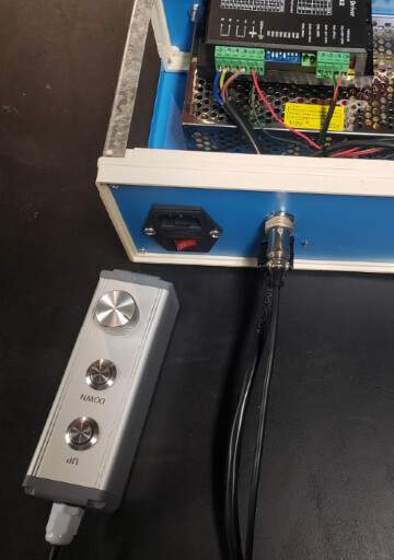
My machine setup is actually quite simple. The tower has a stepper motor that normally connects to the normal socket that controlls up and down manually. When I want to use the Z-control with Easycad/Lightburn I plug it into the rotary socket.
Besides that there is just an Easycad2 light board so nothing special there.
I will make some video’s of what is possible in Lightburn and also of what is possible in Easycad. There are differences; in Easycad I can select a shape/object and assign a Z value to it. This makes is very easy to do different markings on different height levels. Lightburn only lets you mark or cut all layers at one height level, then move the head and start over.
About my supplier; maybe he had a bad day or something haha. I have had a lot of conversations with him and he has been of great help to me to be honest.
hey hey ok gocha the thing I picked up from that is that if I have this right is in lightburn you can set for say a hight and it will zip the glavo up or down or you control it to go up or down.
But in ezcad its an active as its engraving its active?
How is it doing what its doing in Lightburn..
Ok is there an extra plugin you have for ezcad? and lightburn?
Cheers, Im just excited to see you have something working Im sure we would all love to see this, if not a big deal would you care to share you excad? If not all good.
And I wasnt talking to a guy when I was in touch with your supplier it was a girl of somesort and I did not care for her very much.
I think she was being very lazy and sloppy doing her job.
I’ll make a video since it would explain it better than I can with words.
I don’t have extra plugins for either program. Splitmark2 is native to EasyCad as far as I am aware. EasyCad just has more options to use, for example the option to assign Z values to separate shapes/layers. I can mark a square at 10mm height, after that the head moves (for example) 25mm up to do the next mark and after that another 15mm down to do a third mark.
In Lightburn it marks all shapes/layers, then move the head and mark it again. This is fine for cutting and probably for other things too, but if Lightburn would get the option to assign Z values to separate layers/shapes it would be a great improvement in my opinion.
If EasyCad2 can do it, it should be possible in LightBurn right? Again, I am not a programmer, but the entire system is working with an EasyCad2 light board so my guess is it should be possible.
@Hultie
After reading your last post and re-reading a couple of your others, I think I am getting a handle on this. Your speed control is for when you are manually moving the head up or down, with up/ down buttons and maybe a dial to set speed. Am I close?
Then, if you want to use Z stepping, you unplug from the manual adjustment and plug into the rotary port and use “Repeat Marking” At that point your buttons and speed control are not connected. That would explain my misunderstanding when you say you “Lower the speed”
Am I getting close?
This was my original “Non CNC” controller and combined with a DRO worked pretty good until I worked out the bugs for the CNC controller.
Yes you are right
But I’m not sure if I actually should change the speed while using ‘auto Z’. I’m guessing it would give more ‘resolution’ in setting the height if that makes any sense.
If the LightBurn devs would be able (and willing) to implement the option to set Z values in mm’s this wouldn’t be a problem though.
I’m sorry if my explanation doesn’t make too much sense. English isn’t my native language, so sometimes I’m not sure how to describe it accurately
You are doing fine with English. . What is “Auto Z”? if that is when the Z is plugged into the rotary you can smooth it out with speed but not improve resolution.
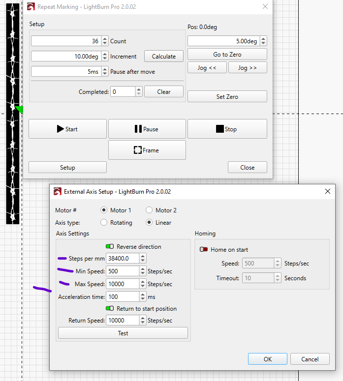
I just popped this up, the numbers are way off for you, for you I would assume “Steps per mm” would be 1280 ( 6400/5 ) if your microstep driver is set to 6400 and you have a 5mm lead screw in the tower.
Min/ Max/ Acceleration speed settings you would use to smooth out the movement WHEN connected to rotary port. Higher number in “Acceleration time” is slower acceleration. I would think Min would be between 100-500, Max would be around 3000, Accel would be around 100-300 with your setup. Fine tuning, I just listen to the motor see what is smoothest.
Never mind my ‘Auto Z’ term. It is just my name for the whole ‘controlling Z movements in software’ haha. Tomorrow or the day after I will check my settings in the menu and play around with them!
After that I selected all of them and opened the SplitMark2 menu again and hit ‘Mark’ to start the job, et voilá:
Some notes
Positioning the shapes with the red light is difficult. When using the ‘Light’ function in SplitMark, the positioning is a few millimeters off compared to when using the 'Light function in the EzCad homescreen. Also; when selecting seperate shapes for the positioning preview the red light is all over the place. Maybe some EzCad bug?
If I select ‘Mark selected’, all shapes are marked on the same X height (all next to each other in line) so it only works without ‘Mark selected’.
The shapes are marked in order as seen in the ‘layers window’
So… in EzCad it is not without it’s quirks, but assigning the Z value for the seperate shapes works very well!
Somewhere in the coming days I will do some testing in LightBurn. I’ll keep you updated.
So that is really cool.
Some comments, of course:
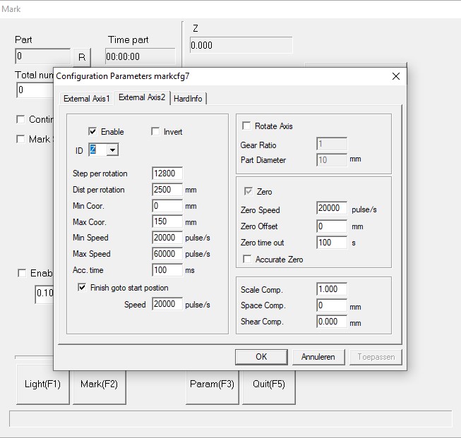
On your setup screen, I see external axis 1, and external axis 2 This would indicate to me that you might have the standard board, not a lite or original. That’s nice if it’s the case.
Your steps per rotation are 12800, distance per rotation is 2500mm. There must be a decimal calculated in there 2500mm per rotation is huge. my tower lead is 5mm per rotation. Looking at the rest of the setup, 20,000 and 60,000 pulses per second are also on the fast side but not out of the range for stepper motors. I run mine at 3000-6000 steps per second on the rotary, on my tower and the XY table I don’t go over 2000.
Looking at these settings is a humbling experience, I know a lot less then I thought I did!
I think the penny might be finally dropping so you are leveraging repeat marking with the stepper if I understand that correctly.
And ezcad has the function for z control separately to lightburn.
So if you were doing say a 2.5 coin engraving you cant leverage the z control but anything else like cutting or vector gfx you can - am I close to the ball park here somewhere or am I a moon away..
And as a by the by thank you so much for posting everything you have and the video amazing effort!!!
Now common lightburn tech boffins!!! give a little back please are we reading this, this thread has been going a little more than a day..
Thats right. 2.5D coins are not possible with this method I suppose. Cutting is possible and works quite well.
With my UV I can get colors on stainless steel with different focus levels, and I used the Z control to mark color at -4mm, and after that -6mm for a nice black mark. It makes that process more predictable and repeatable that way
The cutting will work in Lightburn as well, but the color marking doesn’t because LightBurn can’t handle Z values for different shapes/layers.
If that could be implemented into Lightburn I think there could be quite some potential there for lots of ways of using this.
Peter so the repeat marking couldnt be leveraged as a separate layer? in LB and yes I agree if it works in ezcad it should be able to work in LB as well.
I’m not totally shure about that, I will check. Maybe someone with more experience with the Repeat Marking knows if it’s possible to assign different Repeat Mark settings for seperate layers.
I did some testing in LightBurn and in Easycad. If anyone is interested in details then feel free to ask. I think the video’s show in a simple way what is possible in which software:
LightBurn
I was able to get a cool effect stacking the layers using the Repeat Mark menu:
EzCad2
In EzCad there are a lot more possibilities:
I can imagine that if there is some ‘slicing’ tool that is able to slice an STL into vector layers, then -at least in EzCad-, it would be possible to mimic 3D behaviour. Its not the most elegant method of doing it, but hey. It does work. My testshape consists of 80 layers. It did take 5 minutes or so to assign all the Z values for every seperate shape.
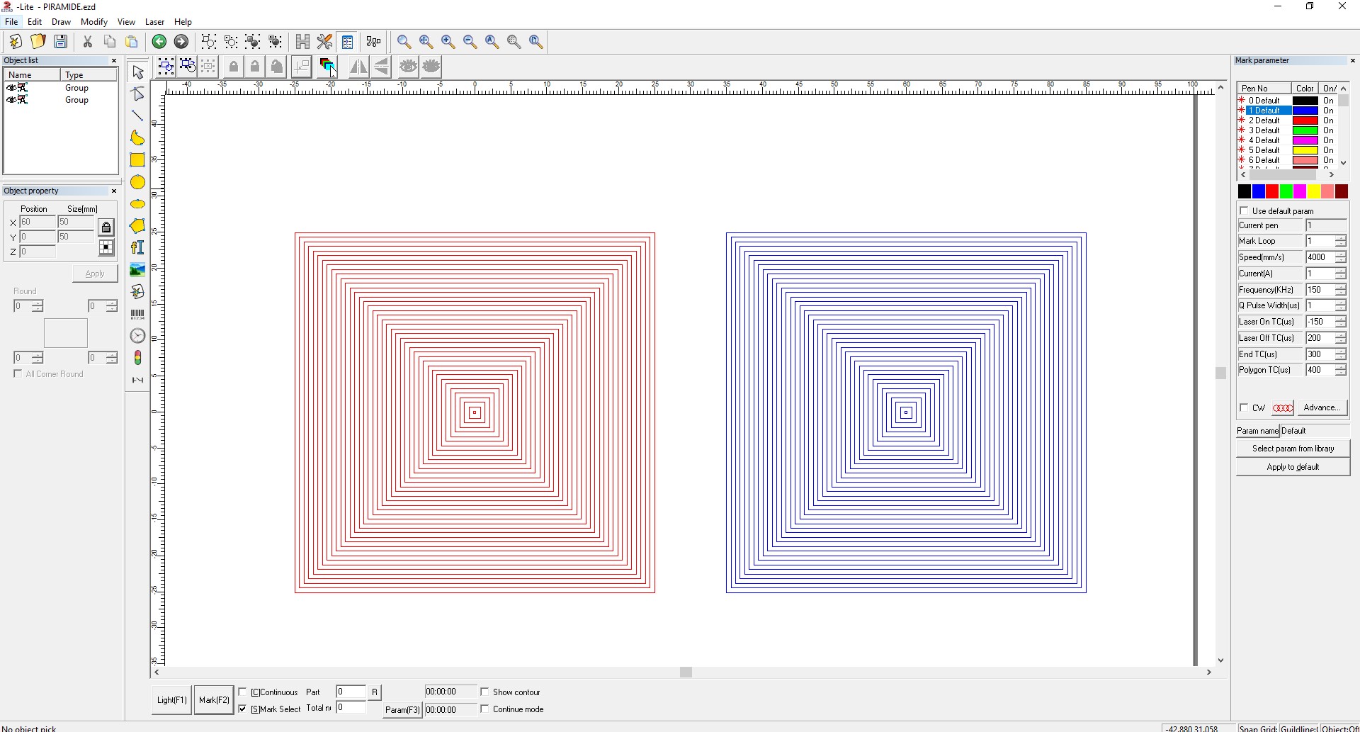
If LightBurn could give us control over the Z values for different shapes that would already be really cool. If they also could write a script that lets you batch import the STL slices (SVG’s, DXF’s or something) in the right order and make it possible to assign Z=0mm for the first ‘layer’ and for example Z=100mm for the last one, and have LB assign Z values to the layer in between automatically… Just dreaming..
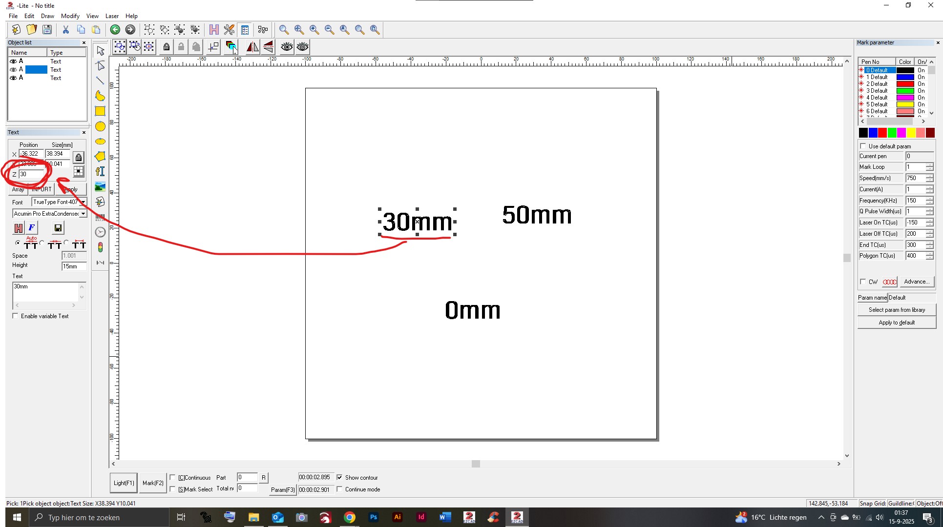
Below a screenshot of what I did for my test. Every square has its own Z value (red is the bottom half of the shape, blue is the top half). When running the test the red and blue shapes were on top of eachother.