dalek
November 18, 2024, 11:36pm
1
I just got a new 100 watt Omtech machine. I finished aligning the mirrors and ran a material test. I’m using the Omtech test card. I had set the text engraving at a speed of 200mms and power at 18% per the manual. This was my starting point. The laser blew through 3mm baltic birch. I adjusted to speed of 300, power 15%, blew through again. There were a few more tries in between and finally tried 600mms, 10%power. The laser still cut through.
Any suggestions?
Thanks!
Dale
jkwilborn
November 18, 2024, 11:45pm
2
Do you have a mA reading at 10% or any of the other settings?
Are you sure you’re setup for mm/s?
dalek
November 19, 2024, 12:47am
3
at 10% power, LPS reads 11Ma. Yes, machine set to mm/s. Omtech manual says it should be 2Ma at 10% power.
Dale
dalek
November 19, 2024, 3:00am
4
I should add that Omtech asked me to measure voltage between G and IN terminals on the LPS while running at 10% powe. It measured .499 volts.
They feel its not the controller but offered no other possibilities.
Dale
ednisley
November 19, 2024, 1:45pm
5
dalek:
at 10% power, LPS reads 11Ma
IN terminals … measured .499 volts.
They feel its not the controller but offered no other possibilities
The HV power supply is the obvious candidate, because the controller is providing the correct PWM signal at 10%.
Despite being a new machine, it arrived with a defective power supply. Get a warranty claim started now and be prepared to take that discussion to the mat.
1 Like
dalek
November 19, 2024, 2:26pm
6
Thanks Ed, I was thinking along the same line
Dale
dalek
November 19, 2024, 3:11pm
7
Hey Ed,
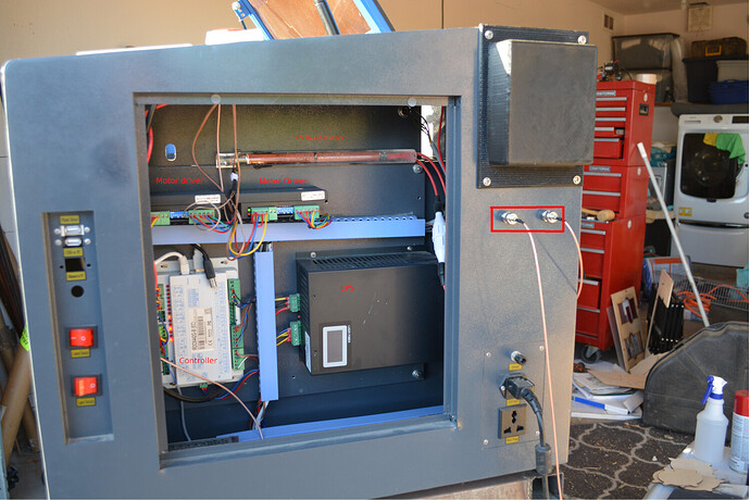
Where is the HV power supply? What does it look like? I can’t find in the manual diagrams or the machine.
Thanks!
Dale
dalek
November 19, 2024, 3:14pm
8
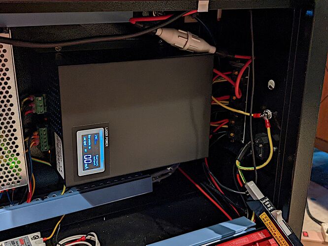
Never mind. It’s part of the laser power supply. This unit needs to be replaced?
Timk5000
November 19, 2024, 3:50pm
9
On My 100 Watt OMTECT the High Voltage is located on the Left Side.
dalek
November 19, 2024, 4:05pm
10
I believe it’s part of the laser power supply
ednisley
November 19, 2024, 5:08pm
12
Depends on the machine layout, but you’re looking for a classic Black Box:
It’ll have a fat red wire to the tube anode and a skinny black wire from the tube cathode.
The green connectors should be unplug / swap supplies / plug and you’re done.
dalek
November 19, 2024, 5:09pm
13
Thanks Jack,
Are the 2 terminals you’ve enclosed in a red rectangle for test? Ed thinks it’s the HV side of the LPS. We’ll see what Omtech thinks.
Dale
jkwilborn
November 19, 2024, 7:50pm
14
It’s likely the lps. The two boxed connectors are 1. generic and used for picking signals, the other is the L-On1 that enables it to lase.

