I am really hoping someone can help me out. I just set up my Genmitsu 5.5w CFL55p Laser on my 3018 Pro machine. I have set up everything according to two Youtube Videos and Lightburns own guide found here . I can manually turn on the laser with the fire button on the laser itself, but the laser will not fire using the fire command on the lightburn software. Further, I can run a whole program through lightburn, the laser will move along the correct x and y paths, but the laser wont fire. My $30 rate is at 1000 mm/min, my device settings are set for mm/min (diode). I am out of ideas. Any help is appreciated, I have a lot of christmas gifts to make.


The actual connections to the laser are suspect.
Where do you get the pwm control for the laser module?
Do you know which controller board you have?
The connections are pretty simple for the laser
It has power, ground and pwm … some have a temperature sensor, but you probably don’t need that.
Since it’s working with the ‘fire’ button, I’d follow the pwm to see where it’s connected. No pwm – no laser output.
Do you have a voltmeter? You can check the pwm with that and see if the controller is putting out the proper control signal…
A photo of the control board (link?) and a link to the laser module would be nice…
I’m assuming you have a ‘laser’ power board which connects to the controller, power for the laser and pwm inputs… This is the ‘fire’ button?
![]()
Jack,
The pwm control came with the laser. Link to laser is here photo below.

I will pick up a voltmeter today and check on that, any tips on how to read that the PMW is getting power, do i read off of the wire or on the board itself?
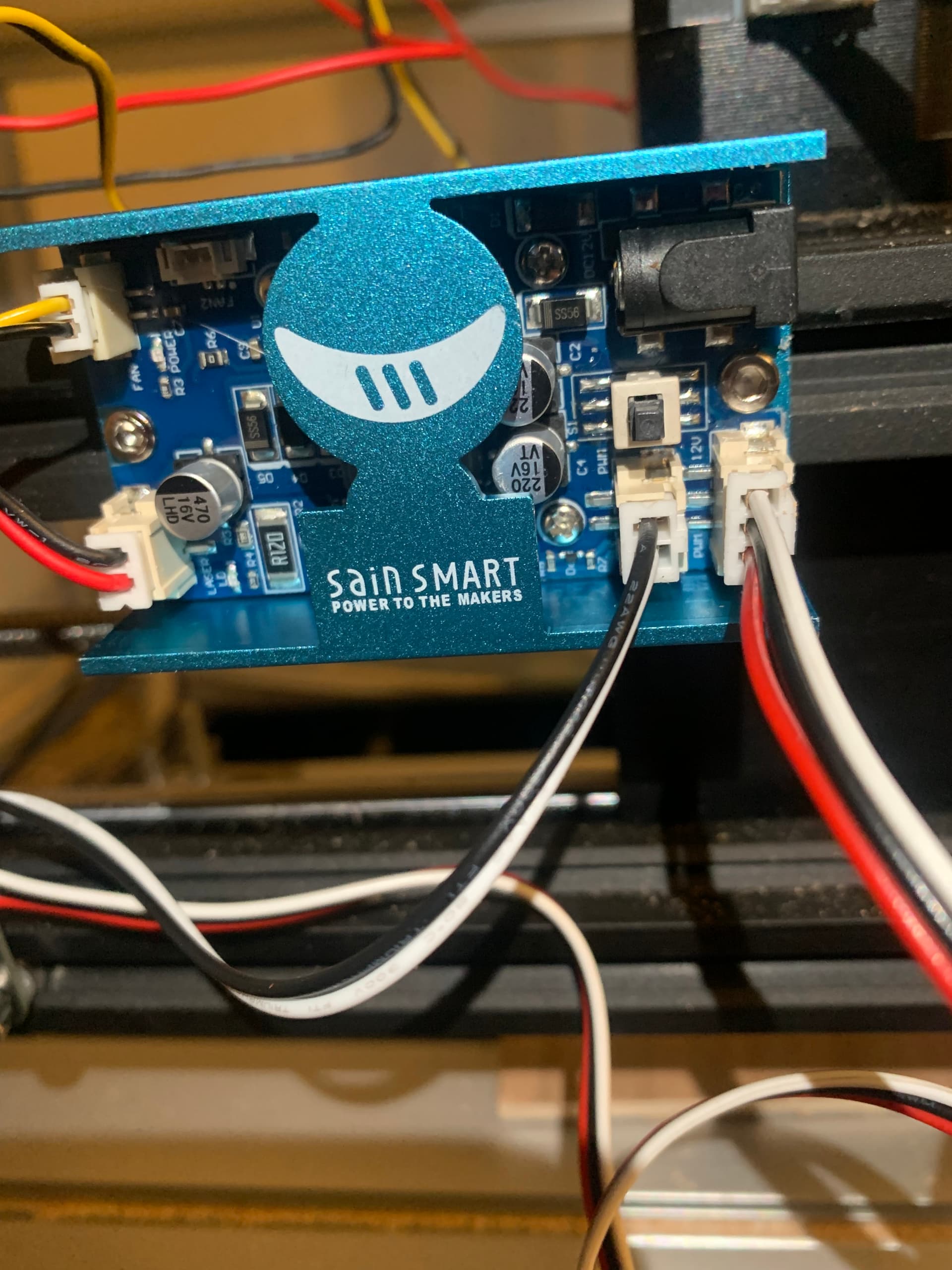
The control board is a GRBL board, the link to the 3018 machine I purchased is here. The images show multiple boards but the board i got is pictured below.
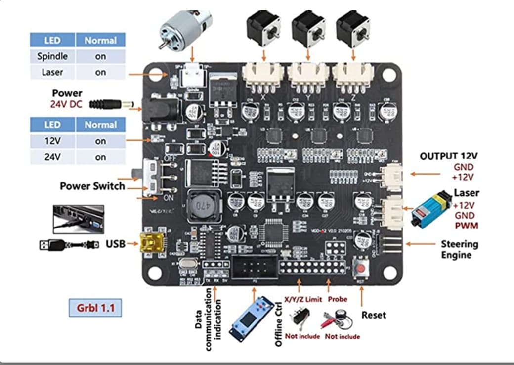
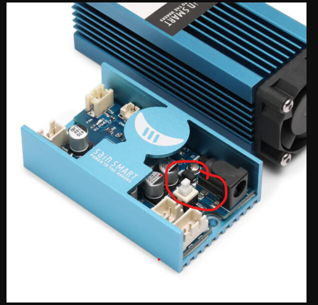
The “Fire button” is on the laser power board and can be pictured in the photo below
Thanks for responding, I will test out the connections tonight.
What is the behaviour of the spindle / laser light on the control board? (top left of picture)
John, by behavior do you mean the status of the light? unfortunately i am not at the machine right now but last night when i was trouble shooting it was on, and at some points flashing. If this is not what you are talking about some more detail would be good.
Thanks!
You’re right - that’s an indicator light… Thanks!
The more I look at the board, it appears these are led indicators for spindle and laser…
It’s real common to have these cables wired incorrectly… I’d follow the cable colors and make sure all there are going to where they should…
The pwm is the way we control the laser, commonly though the power setting of the layer… It is generated by the control board.
You can measure the pwm anywhere you can get to the signal pin.
It’s easy to ‘short’ out stuff with large probes so be more than careful…
Measure from ground to the pwm output. It is a ttl voltage (0 - 5V) input signal. At 50% pwm it should measure 50% of the voltage or 2.5V … 30% 1.5V
Make sense?
![]()
Jack,
Thanks for all your help, that does make sense, i will get a voltmeter tonight and check that out. The kit that the laser came with had two 3 pin connectors, one where all three colors ran into the same pins (pin 1 to pin 1, 2 to 2, 3 to 3) and another 3 pin kit labeled 3018Pro where the black and white lines were flipped (1 to 2, 2 to 1, 3 to 3). I followed the packet instruction and used the one labeled 3018 pro, I’m thinking now this may have caused a short.
If i did short the board, what are my next steps? Do i have to get a new GRBL board to run the laser or is there another fix.
Really appreciate the help.
I doubt you damaged the board… I’d continue with the assumption that the hardware is ok and the problem is the connections/mis-wire. At least until we determine otherwise.
You can follow from where the 12V, ground and pwm come out of your board on the connector…
Look at how the plug goes into the connector and follow that line to the other end… when it’s oriented correctly do the proper pins line up?
With a meter you can ‘ohm’ them out if you can’t follow them with your eyes.
It’s always possible you got a bad unit or there are other problems but these are pretty dependable…
If you’re unsure, ask…
![]()
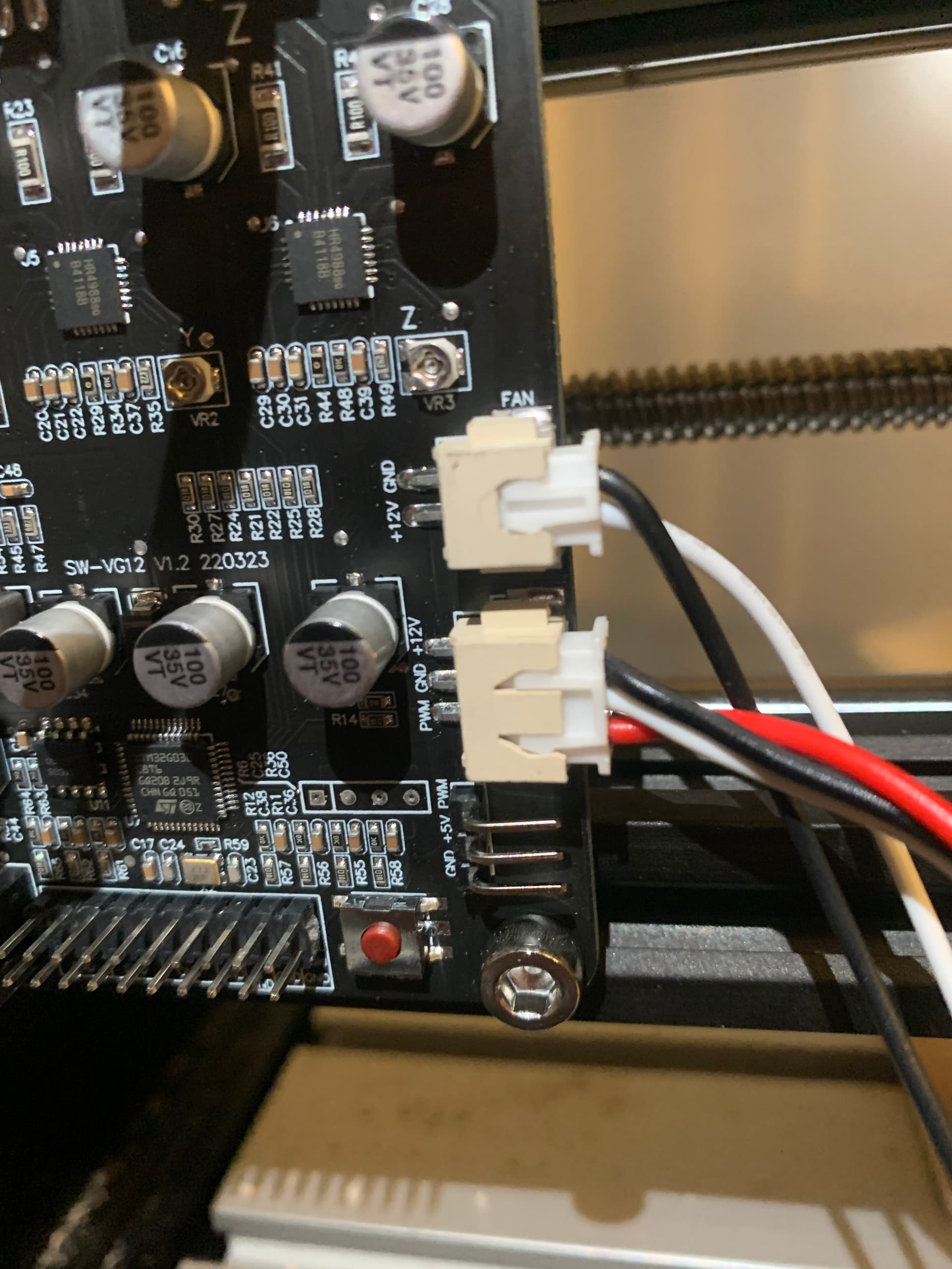
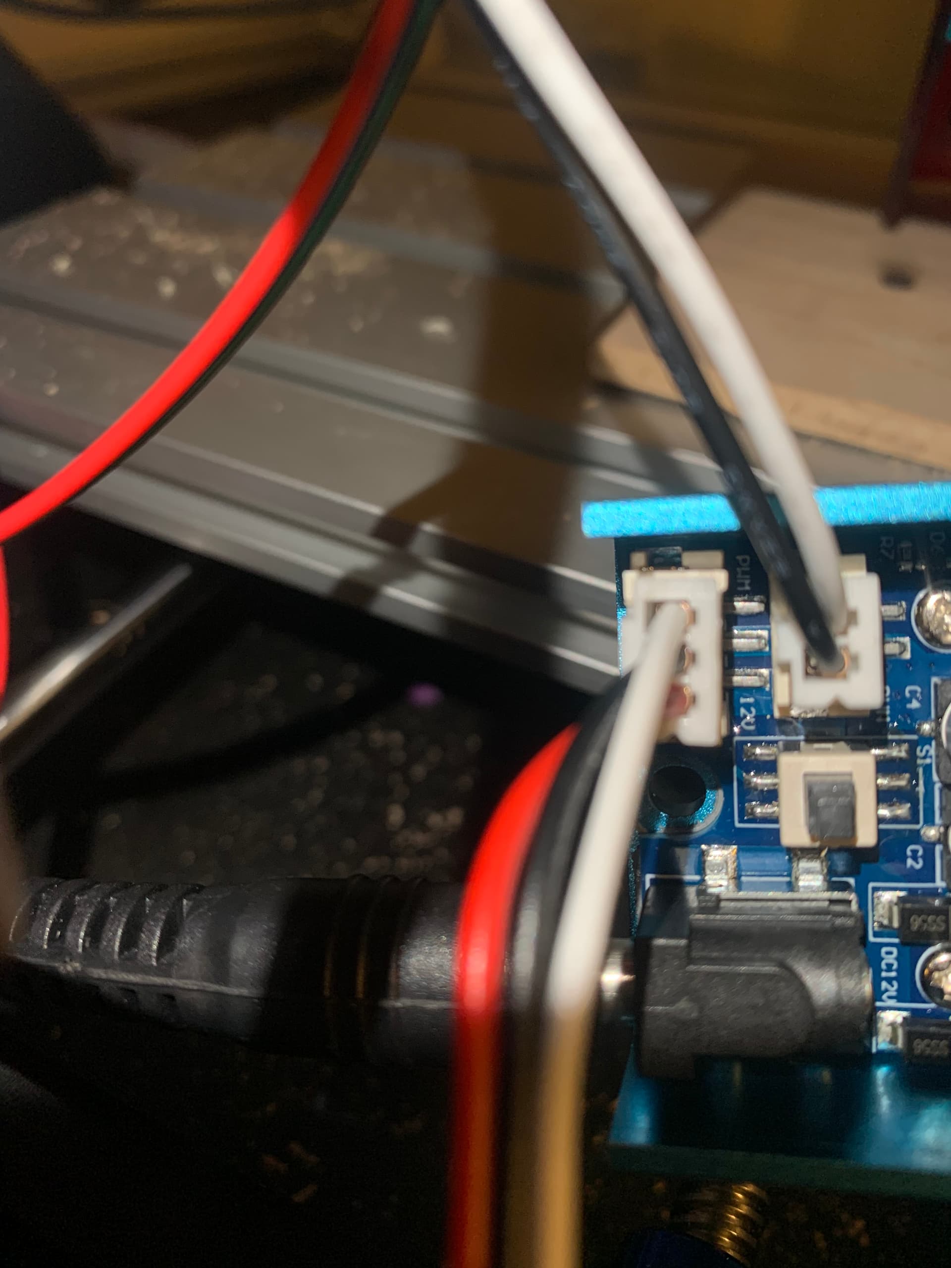
Alright, so I got the Voltmeter and I think i’m more confused then when i started. I can not get a reading off of the GBRL board. I have the fire button on Lightburn on, reading from 12v to ground, nothing. I decided to try the other three pin connecter that came with the laser and it shorts the power board for the laser. Below i have two pictures; the first is the three pin on the GRBL board, second the three pin on the power module. Notice how red is PMW on the GRBL board, and its 12v on the power board. I have another 3 pin that is a normal 3 pin, but when i plug that in it shorts the power module…
My questions are;
- which is the right three pin
- If i cant read power on the GRBL board for the three pin how am i shorting out the power board
- what do i do now?
Thanks!
I think your photos have all the wiring information we need…
I know, from the controller photo, the black wire is 12V, white is ground and red is pwm from the
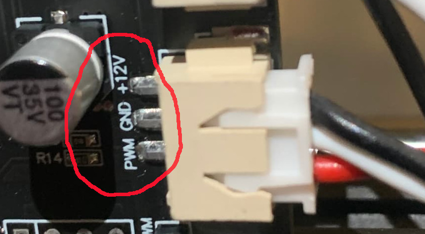
Looking closely at the ‘control’ module for the laser I can deduce that you have white (ground on controller), black (12V) is wired to ground and red (pwm) wired to 12V… This is an issue… ![]()

Do you see what I’m seeing?
The PWM of the controller to PWM of the control board, GND of the controller board to, what has to be GND of the control board. You only need these two.
With your setup, you don’t need the 12V connection… only ground and pwm.
You can usually remove the pins and ‘rearrange’ them to the proper order or slot… Usually doesn’t look pretty but it’s entirely functional…
@ednisley … I guess they use what they have on hand…
![]()
Wisely is it written about wire “color codes”: Hell hath no fury like that of an unjustified assumption.
Move your S-value max to 10000
“You might need to adjust your spindle max RPM value ($30) to match the LightBurn default (1000) or vice versa. The value in LightBurn is called “S-Value Max”, in the Device Settings.”
Lightburn common grbl setup documentation…
![]()
I had a similar problem with the laser not working and by upping the S-value to 10000, it made it work. It burns everything now. Just a thought, if after looking into the wiring and if it’s still not working maybe that’s something that could be looked at.
S-value max needs to be set equal to $30… or vice versa…
![]()
@jkwilborn I see exactly what you’re seeing, and think i understand what you’re saying. Let me ask you one more question. I have another three pin wire that has the correct wiring. I have connected it to the control board and the power board in the below pictures. This may be a dumb question, but instead of messing with the pins can i just cut the 12v to 12v wire since i don’t need it?
Currently if i turn on power to the control board and the power board (both connected to separate 12v power sources) the power board shorts out, but as soon as i unplug the three pin it powers back up.

Generally speaking, yes you could cut it … I always stay away from permanent damage… if possible. It would be a drag to find out we need it… even though I don’t think so…
However you can remove the 12V line and tape the end up…
Here’s a 6min video of pulling a pin out of a connector… There is an ‘ear’ that sticks up from the crimped on connector… you only need to press it down and pull (gently) on the wire…

These are for rc cars but most of them work this way…
Is it not powering up with the new wiring?
![]()
@jkwilborn thanks i will do it the right way after work today and report back if it works.
Currently if i plug in this three pin it shorts out the power board for the laser, i think its because of the 12v, to the 12v connection.
I will try it out and let you know what the results are.
Thanks mate
@jkwilborn just removed the pins for the 12v to 12v connection and it still isn’t working unfortunately. Not sure where to go from here other than getting a new GRBL board, unless you have any other suggestions.